Arduino Development Board Version Two

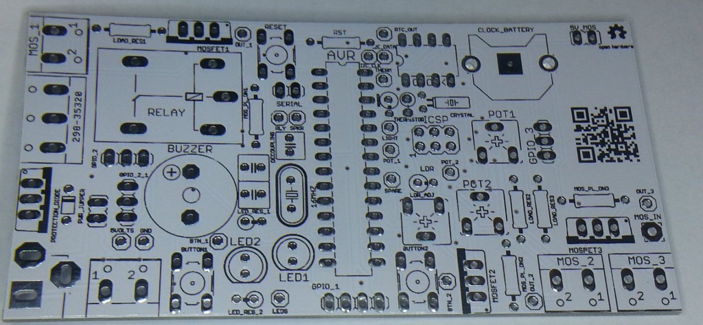
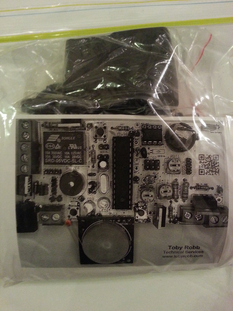
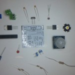
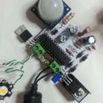
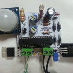
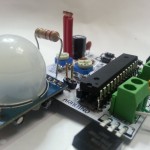
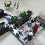
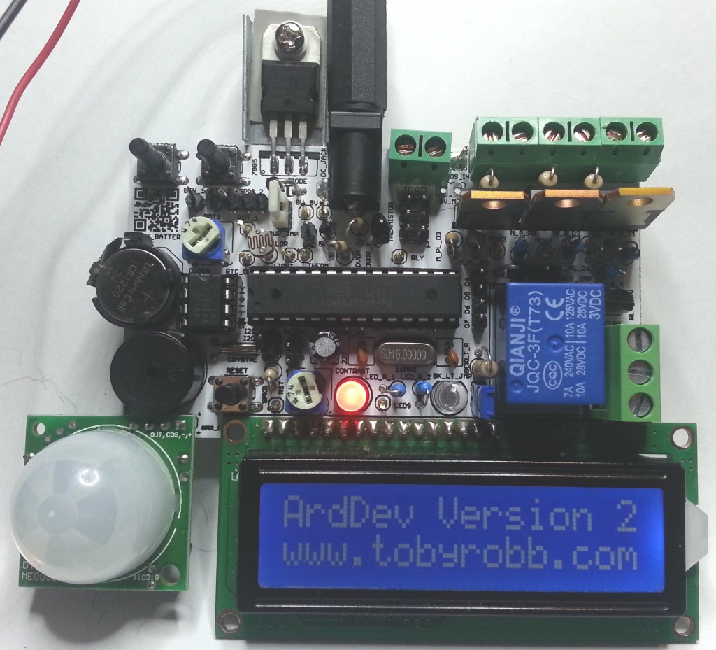
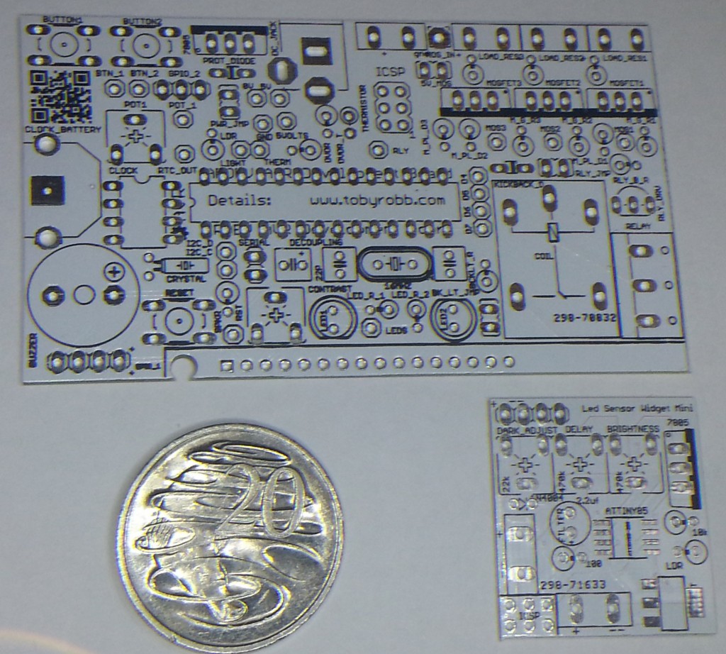
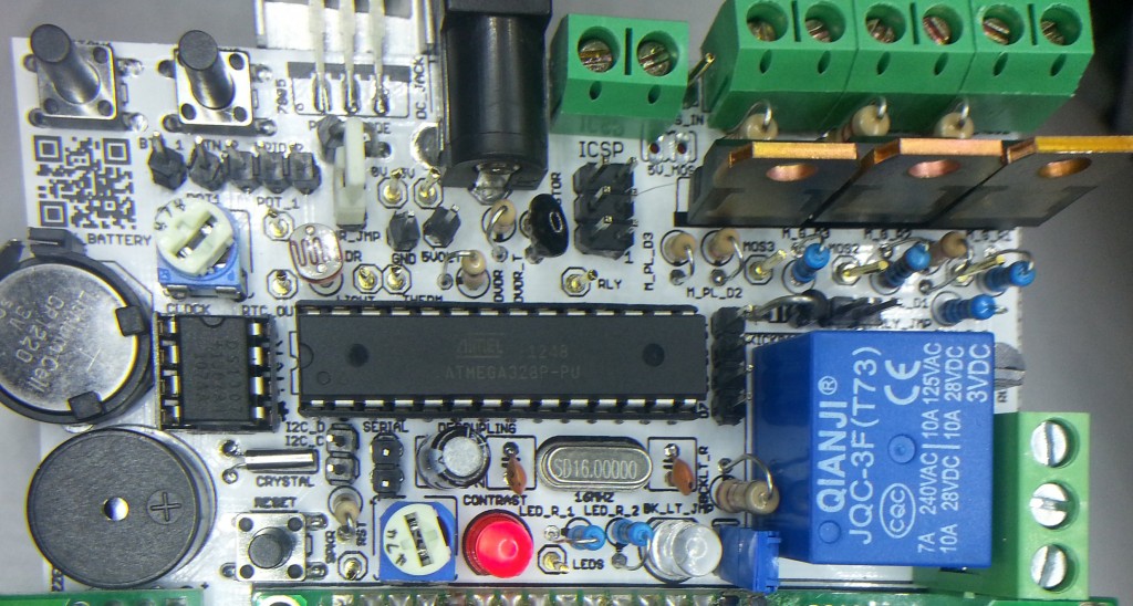
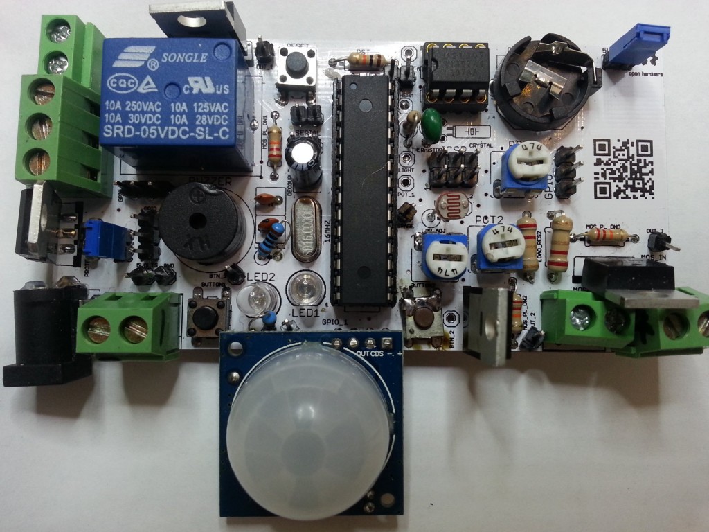
Here are some pics of the second version of my Arduino Development Board.

Very happy with the board, everything is working great, and its really feature packed!

It has got..

An LCD, a buzzer, 2 status leds, a potentiometer, a real time clock with battery backup, a high power relay (230v 10A), 3 high power PWM capable mosfets (60v 16A), 2 buttons, a temperature sensor, a movement sensor, a light sensor, a servo connector.

All pins are broken out to test headers. There is a on board 5v 1A supply with 7-35v DC barrel jack input or screw terminals. The relays and mosfet have screw terminals. The mosfets can be also supplied with an indepent voltage source.

Some of the uses if have put it to are :-

An LCD menu based Morse keyer/beacon.

An LCD based time clock with an alarm clock relay and bluetooth reporting and control.

An LCD based thermostat controller.

An LCD base RGB lighting controller.

A movement night sensor LED light.

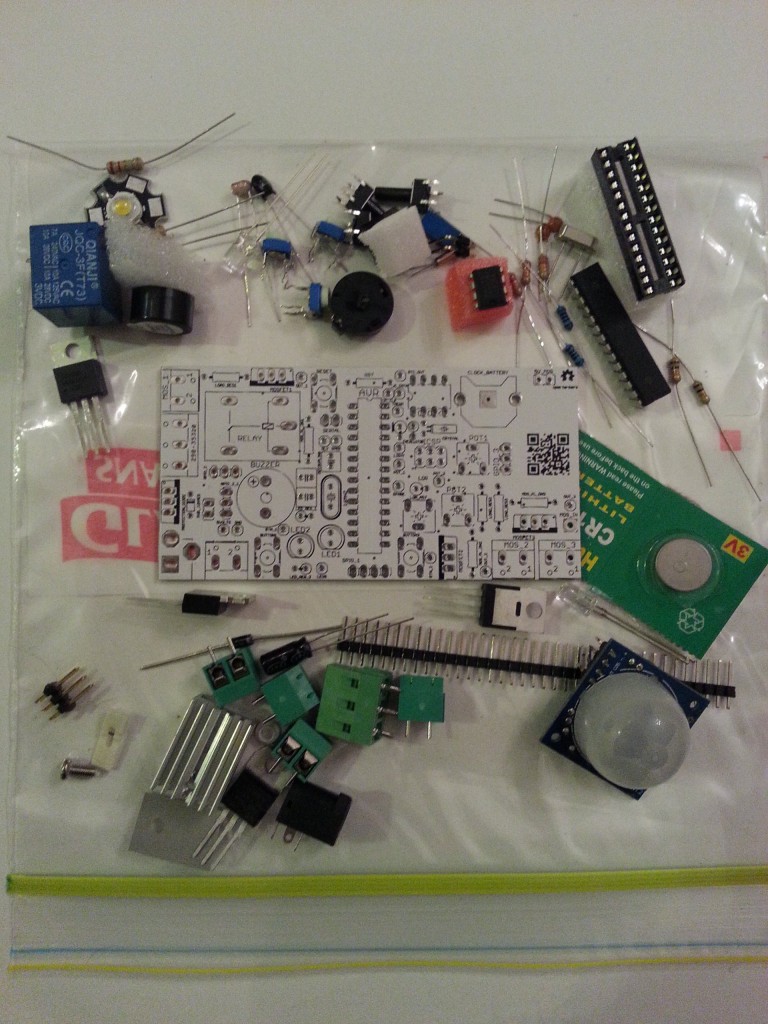
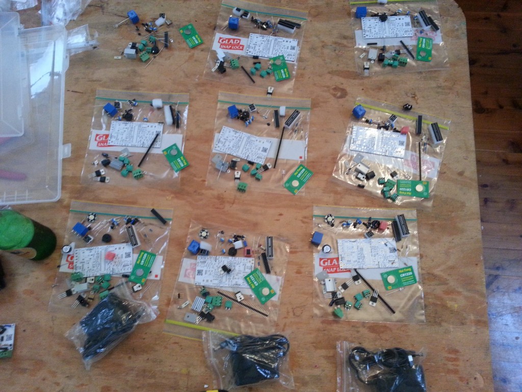
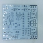
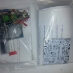
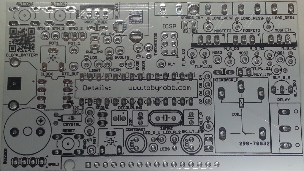
I got 10 PCB’s printed and sourced the parts for 10 kits. I can sell you some parts kits, ranging from $2 bare PCB only to about $40 for all the parts including a plug pack.

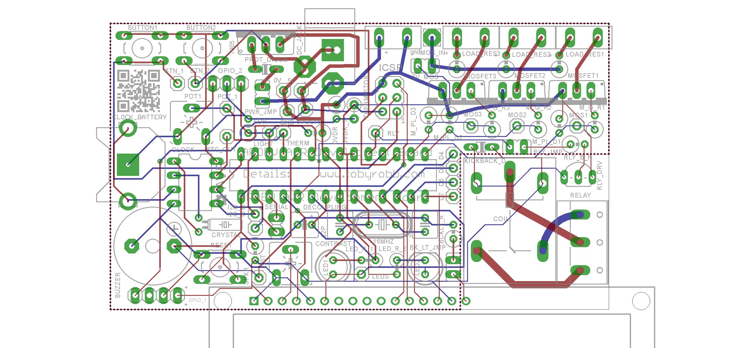
If you are interested in the design files for Eagle, or the gerber’s so you can print them off yourself, email me.

I really went to town with the code, i had my first attempt at using preprocessor directives to allow people to uncomment a config section to enable or disable periphals on the board, depending on what they have soldered in. For those who are interested i have posted my test sketch at the bottom.

Populated PCB_LAYOUT ARDEV2_top ARDEV2_bottom pcbs Populated_close_up


/*

25 December 2013

Toby Robb

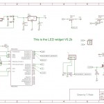
This is a test sketch for the Arduino Development board version 2

TODO LIST

Nothing yet

NOTES:

UNCOMMENT the correct sections for the peripherals you have installed
LED / LCD is the same pin, have only one or the other, is the LCD enable pin
RELAY is also the SCK pin *therefore may need to REMOVE relay jumper for programming
THERMISTOR / MOVEMENT SENSOR is the same pin, have only one or the other
LDR / SERVO is the same pin, have only one or the other

you must enable the internal pullups for the buttons by setting as inputs then writing HIGH
The leds if fitted also require the pullups to be enabled

*/

// Includes

#include <Servo.h> // Include the servo library
#include <Wire.h>
#include “RTClib.h” // For the clock
#include <LiquidCrystal.h> //for the LCD

//UNCOMMENT the correct sections for the peripherals you have installed
//PIR OR THERMISTOR not both
//LCD OR LED not both
//LDR OR SERVO not both
#define USE_LCD //uncomment this line if you have an LCD installed — NO leds at same time allowed
//#define USE_LED //uncomment this line if LED is installed — NO lcd at same time allowed

#define USE_PIR //uncomment this line if PIR is installed — NO thermistor at same time allowed
//#define USE_THERMISTOR //uncomment this line if THERMISTOR is installed — NO pir at same time allowed

#define USE_LDR //uncomment this line to use Light Dependent Resistor — NO servo at same time
//#define USE_SERVO //uncomment this line to use servo — NO ldr at same time
#define USE_BUZZER // uncomment this line to use BUZZER
#define USE_RTC // uncomment this line if the real time clock is fitted
#define USE_POT // uncomment this line to use POT (4:20!
#define USE_RELAY // uncomment this line to use RELAY

#define USE_BUTTON1 // uncomment this line to use BUTTON 1
#define USE_BUTTON2 // uncomment this line to use BUTTON 2

#define USE_MOS1 // uncomment this line to use MOSFET 1
#define USE_MOS2 // uncomment this line to use MOSFET 2
#define USE_MOS3 // uncomment this line to use MOSFET 3

RTC_DS1307 RTC; // Date and time functions using a DS1307 RTC connected via I2C and Wire lib

/* initialize the lcd library with the numbers of the interface pins
* LCD RS pin to digital pin 2
* LCD Enable pin to digital pin 4 //also the LED pin.. OFF to enable LCD
* LCD D4 pin to digital pin 5
* LCD D5 pin to digital pin 6
* LCD D6 pin to digital pin 7
* LCD D7 pin to digital pin 8
*/
LiquidCrystal lcd(2, 4, 5, 6, 7, 8); // Test code for LCD may need to be commented IN, LED code commented OUT

Servo servo1; // create servo object to control a servo
// a maximum of eight servo objects can be created
int servoPos = 0; // variable to store the servo position

// Defines

#define ldrPin A3 // Light dependant resistor pin on board.
#define thermistorPin A2 //Temperature thermistor pin on board.
#define ledPin 4 // Led pin High for one colour Low for another
#define buzzerPin A1 // The onboard buzzer pin
#define relayPin 13 // Pin for the relay

#define dataPin A4 // The I2C bus DATA pin
#define clockPin A5 // The I2C CLOCK pin

#define potPin A0 // Potentiometer on the board.

#define button1Pin 12 // Button 1 pin
#define button2Pin 11 // Button 2 pin

#define gpio1Pin A2 // General Purpose Input/output 1 pin
#define gpio2Pin A3 // General Purpose Input/output 2 pin

#define mosfet1Pin 3 // Mosfet 1 drive pin
#define mosfet2Pin 9 // Mosfet 2 drive pin
#define mosfet3Pin 10 // Mosfet 3 drive pin

// declare some variables here if you like

void setup(){

// Setup the serial

Serial.begin(9600);
Serial.println(“Beginning Setup”);

// Set up the pins

pinMode(ldrPin, INPUT); // If the light sensor resistor is fitted
pinMode(thermistorPin, INPUT); // If the temperature sensor resistor is fitted
pinMode(ledPin, OUTPUT); // You MUST use this if the LED’s are fitted.
pinMode(relayPin, OUTPUT); // If the relay is fitted.
pinMode(buzzerPin, OUTPUT); // If the buzzer is fitted.
pinMode(potPin, INPUT); // If the potentiometer is fitted
pinMode(button1Pin, INPUT); // If the button is fitted (write HIGH to enable pullups)
pinMode(button2Pin, INPUT); // If the button is fitted (write HIGH to enable pullups)
pinMode(mosfet1Pin, OUTPUT); // Mosfet 1 output
pinMode(mosfet2Pin, OUTPUT); // Mosfet 2 output
pinMode(mosfet3Pin, OUTPUT); // Mosfet 3 output

// default states

digitalWrite(dataPin, HIGH);
digitalWrite(clockPin, HIGH);
digitalWrite(relayPin, LOW);
digitalWrite(button1Pin, HIGH); // enables pullups for buttons
digitalWrite(button2Pin, HIGH); // enables pullups for buttons
#ifdef USE_LED
digitalWrite(ledPin, LOW); //enables pullups for LED’s
#endif

// set up the LCD’s number of columns and rows:
#ifdef USE_LCD
lcd.begin(16, 2);
lcd.clear();
#endif

#ifdef USE_SERVO
servo1.attach(gpio2Pin); // attaches the servo on pin gpio 2 to the servo object
servo1.write(0); //set servo to initial position
#endif

#ifdef USE_RTC
Wire.begin();
RTC.begin();
if (! RTC.isrunning()) {
Serial.println(“RTC is NOT running!”);
// uncommenting the following line sets the RTC to the date & time this sketch was compiled
// RTC.adjust(DateTime(__DATE__, __TIME__));
}
#endif

}

void loop(){

//lets do some error checking of the board hardware

#ifdef USE_LCD
#ifdef USE_LED
Serial.println(“CONFLICT! LCD and LEDS together is not allowed”);
lcd.setCursor(0,0);
lcd.print(“CONFLICT LCD/LED”);
lcd.setCursor(0,1);
lcd.print(“NOT BOTH AT ONCE”);
delay(5000);
#endif
#endif

#ifdef USE_PIR
#ifdef USE_THERMISTOR
Serial.println(“CONFLICT! PIR and THERMISTOR together is not allowed”);
lcd.setCursor(0,0);
lcd.print(” !! CONFLICT !! “);
lcd.setCursor(0,1);
lcd.print(“PIR + THERMISTOR”);
delay(5000);
#endif
#endif

#ifdef USE_LDR
#ifdef USE_SERVO
Serial.println(“CONFLICT! LDR and SERVO together is not allowed”);
lcd.setCursor(0,0);
lcd.print(” !! CONFLICT !! “);
lcd.setCursor(0,1);
lcd.print(” LDR + SERVO “);
delay(5000);
#endif
#endif

// Begin

#ifdef USE_LCD
lcd.clear();
lcd.setCursor(0,0);
lcd.print(“ArdDev Version 2″);
lcd.setCursor(0,1);
lcd.print(“www.tobyrobb.com”);
delay(3000);
#endif

#ifdef USE_LCD
lcd.clear();
lcd.setCursor(0,0);
lcd.print(“ArdDev Version 2″);
lcd.setCursor(0,1);
lcd.print(” Beeping buzzer “);
#endif

//beep the buzzer

#ifdef USE_BUZZER
Serial.println(“Beep”);
tone(buzzerPin, 500); // begin tone at 1000 hertz
delay(150); // wait half a sec
noTone(buzzerPin); // end beep
delay(2000);
#endif
//Print the time and date to the serial port
#ifdef USE_RTC
DateTime now = RTC.now();

Serial.print(now.year(), DEC);
Serial.print(‘/’);
Serial.print(now.month(), DEC);
Serial.print(‘/’);
Serial.print(now.day(), DEC);
Serial.print(‘ ‘);
Serial.print(now.hour(), DEC);
Serial.print(‘:’);
Serial.print(now.minute(), DEC);
Serial.print(‘:’);
Serial.print(now.second(), DEC);
Serial.println();

#ifdef USE_LCD
lcd.clear();
lcd.setCursor(0,0);
lcd.print(“Time: “);
lcd.setCursor(6,0);
lcd.print(now.hour(), DEC);
lcd.setCursor(8,0);
lcd.print(“:”);
lcd.setCursor(9,0);
lcd.print(now.minute(), DEC);
lcd.setCursor(0,1);
lcd.print(“Date: “);
lcd.setCursor(6,1);
lcd.print(now.day(), DEC);
lcd.setCursor(8,1);
lcd.print(“:”);
lcd.setCursor(9,1);
lcd.print(now.month(), DEC);
lcd.setCursor(11,1);
lcd.print(“:”);
lcd.setCursor(12,1);
lcd.print(now.year(), DEC);
delay(5000);
#endif
#endif

#ifdef USE_LED
//flash the leds
lcd.clear();
lcd.setCursor(0,0);
lcd.print(“ArdDev Version 2″);
lcd.setCursor(0,1);
lcd.print(” Flash the leds “);
Serial.println(“Flash the LED’s”);
for(int i = 0; i<=8; i++){
digitalWrite(ledPin, HIGH); // turn the LED on (HIGH is the voltage level)
delay(100); // wait for a second
digitalWrite(ledPin, LOW); // turn the LED off by making the voltage LOW
delay(100); // wait for a second
}
digitalWrite(ledPin, LOW); // turn the LED off ALSO LCD enable

delay(2000);
#endif
// Cycle the relay
#ifdef USE_RELAY
#ifdef USE_LCD
lcd.clear();
lcd.setCursor(0,0);
lcd.print(“ArdDev Version 2″);
lcd.setCursor(0,1);
lcd.print(” Relay ON “);
#endif
digitalWrite(relayPin, HIGH);
Serial.println(“Relay ON”);
delay(2000);
digitalWrite(relayPin, LOW);
Serial.println(“Relay OFF”);
#ifdef USE_LCD
lcd.setCursor(0,1);
lcd.print(” Relay OFF “);
#endif
delay(2000);
#endif

// Sweep the servo on GPIO 2
#ifdef USE_SERVO

#ifdef USE_LCD
lcd.clear();
lcd.setCursor(0,0);
lcd.print(“ArdDev Version 2″);
lcd.setCursor(0,1);
lcd.print(“Sweep servo “);
lcd.setCursor(12,1);
#endif

for(servoPos = 0; servoPos < 180; servoPos += 1) // goes from 0 degrees to 180 degrees
{ // in steps of 1 degree
servo1.write(servoPos); // tell servo to go to position in variable ‘servoPos’
if((servoPos>=0) && (servoPos<=9)){
#ifdef USE_LCD
lcd.setCursor(12,1);
lcd.print(servoPos);
lcd.setCursor(13,1);
lcd.print(” “);
#endif
}
if((servoPos>=10) && (servoPos<=99)){
#ifdef USE_LCD
lcd.setCursor(12,1);
lcd.print(servoPos);
lcd.setCursor(14,1);
lcd.print(” “);
#endif
}
if((servoPos>=100) && (servoPos<=999)){
#ifdef USE_LCD
lcd.setCursor(12,1);
lcd.print(servoPos);
lcd.setCursor(15,1);
lcd.print(” “);
#endif
}
if(servoPos>=1000){
#ifdef USE_LCD
lcd.setCursor(12,1);
lcd.print(servoPos);
#endif
}
Serial.print(“Sweep the servo “);
Serial.println(servoPos);
delay(5); // waits 15ms for the servo to reach the position
}
for(servoPos = 180; servoPos>=1; servoPos-=1) // goes from 180 degrees to 0 degrees
{
servo1.write(servoPos); // tell servo to go to position in variable ‘servoPos’
if((servoPos>=0) && (servoPos<=9)){
#ifdef USE_LCD
lcd.setCursor(12,1);
lcd.print(servoPos);
lcd.setCursor(13,1);
lcd.print(” “);
#endif
}
if((servoPos>=10) && (servoPos<=99)){
#ifdef USE_LCD
lcd.setCursor(12,1);
lcd.print(servoPos);
lcd.setCursor(14,1);
lcd.print(” “);
#endif
}
if((servoPos>=100) && (servoPos<=999)){
#ifdef USE_LCD
lcd.setCursor(12,1);
lcd.print(servoPos);
lcd.setCursor(15,1);
lcd.print(” “);
#endif
}
if(servoPos>=1000){
#ifdef USE_LCD
lcd.setCursor(12,1);
lcd.print(servoPos);
#endif
}
Serial.print(“Sweep the servo “);
Serial.println(servoPos);
delay(5); // waits 15ms for the servo to reach the position
}
delay(2000);
#endif

// Print the value of the button states
#ifdef USE_BUTTON1
#ifdef USE_LCD
lcd.clear();
#endif
for(int i = 0; i <=200; i++){
#ifdef USE_LCD
lcd.setCursor(0,0);
lcd.print(” Button 1 State “);
if(digitalRead(button1Pin)==HIGH){
lcd.setCursor(0,1);
lcd.print(” OFF “);
}
if(digitalRead(button1Pin)==LOW){
lcd.setCursor(0,1);
lcd.print(” ON “);
}
#endif
Serial.print(“Button one state : “);
Serial.println(digitalRead(button1Pin));
}
delay(2000);
#endif

#ifdef USE_BUTTON2
#ifdef USE_LCD
lcd.clear();
#endif
for(int i = 0; i <=200; i++){
#ifdef USE_LCD
lcd.setCursor(0,0);
lcd.print(” Button 2 State “);
if(digitalRead(button2Pin)==HIGH){
lcd.setCursor(0,1);
lcd.print(” OFF “);
}
if(digitalRead(button2Pin)==LOW){
lcd.setCursor(0,1);
lcd.print(” ON “);
}
#endif
Serial.print(” Button two state : “);
Serial.println(digitalRead(button2Pin));
}
delay(2000);
#endif

// Show the value of the LDR for a few seconds
#ifdef USE_LDR
#ifdef USE_LCD
lcd.clear();
lcd.setCursor(0,0);
lcd.print(“ArdDev Version 2″);
lcd.setCursor(0,1);
lcd.print(“Brightness “);
#endif
for(int i = 0; i <=500; i++){
if((analogRead(ldrPin)>=0) && (analogRead(ldrPin)<=9)){
#ifdef USE_LCD
lcd.setCursor(12,1);
lcd.print(analogRead(ldrPin));
lcd.setCursor(13,1);
lcd.print(” “);
#endif
}
if((analogRead(ldrPin)>=10) && (analogRead(ldrPin)<=99)){
#ifdef USE_LCD
lcd.setCursor(12,1);
lcd.print(analogRead(ldrPin));
lcd.setCursor(14,1);
lcd.print(” “);
#endif
}
if((analogRead(ldrPin)>=100) && (analogRead(ldrPin)<=999)){
#ifdef USE_LCD
lcd.setCursor(12,1);
lcd.print(analogRead(ldrPin));
lcd.setCursor(15,1);
lcd.print(” “);
#endif
}
if(analogRead(ldrPin)>=1000){
#ifdef USE_LCD
lcd.setCursor(12,1);
lcd.print(analogRead(ldrPin));
#endif
}
Serial.print(“The Brightness : “);
Serial.println(analogRead(ldrPin));
}
delay(2000);
#endif

#ifdef USE_PIR
#ifdef USE_LCD
lcd.clear();
lcd.setCursor(0,0);
lcd.print(“ArdDev Version 2″);
lcd.setCursor(0,1);
#endif
for(int i = 0; i <=600; i++){
if(analogRead(thermistorPin)>=127){
#ifdef USE_LCD
lcd.setCursor(0,1);
lcd.print(“Movement detect!”);
#endif
Serial.print(“Movement detected! “);
}
if(analogRead(thermistorPin)<=126){
#ifdef USE_LCD
lcd.setCursor(0,1);
lcd.print(” No Movement “);
#endif
Serial.print(“NO Movement detected “);
}
Serial.println(analogRead(thermistorPin));
}

#endif
#ifdef USE_THERMISTOR
//show the value of the temperature thermistor for a few seconds
#ifdef USE_LCD
lcd.clear();
lcd.setCursor(0,0);
lcd.print(“ArdDev Version 2″);
lcd.setCursor(0,1);
lcd.print(“Degrees C “);
lcd.setCursor(0,1);
#endif
for(int i = 0; i <=500; i++){
if((Thermistor(analogRead(thermistorPin))>=0) && (Thermistor(analogRead(thermistorPin))<=9)){
#ifdef USE_LCD
lcd.setCursor(12,1);
lcd.print(Thermistor(analogRead(thermistorPin)));
lcd.setCursor(13,1);
lcd.print(” “);
#endif
}
if((Thermistor(analogRead(thermistorPin))>=10) && (Thermistor(analogRead(thermistorPin))<=99)){
#ifdef USE_LCD
lcd.setCursor(12,1);
lcd.print(Thermistor(analogRead(thermistorPin)));
lcd.setCursor(14,1);
lcd.print(” “);
#endif
}
if((Thermistor(analogRead(thermistorPin))>=100) && (Thermistor(analogRead(thermistorPin))<=999)){
#ifdef USE_LCD
lcd.setCursor(12,1);
lcd.print(analogRead(thermistorPin));
lcd.setCursor(15,1);
lcd.print(” “);
#endif
}
if(Thermistor(analogRead(thermistorPin))>=1000){
#ifdef USE_LCD
lcd.setCursor(12,1);
lcd.print(analogRead(thermistorPin));
#endif
}

Serial.print(“The Temperature : “);
Serial.println(analogRead(thermistorPin));
}
delay(2000);
#endif
// Print off the potentiometer value for a few seconds
#ifdef USE_POT
#ifdef USE_LCD
lcd.clear();
lcd.setCursor(0,0);
lcd.print(“ArdDev Version 2″);
lcd.setCursor(0,1);
lcd.print(“Pot “);
lcd.setCursor(0,1);
#endif
for(int i = 0; i <=500; i++){
if((analogRead(potPin)>=0) && (analogRead(potPin)<=9)){
#ifdef USE_LCD
lcd.setCursor(12,1);
lcd.print(analogRead(potPin));
lcd.setCursor(13,1);
lcd.print(” “);
#endif
}
if((analogRead(potPin)>=10) && (analogRead(potPin)<=99)){
#ifdef USE_LCD
lcd.setCursor(12,1);
lcd.print(analogRead(potPin));
lcd.setCursor(14,1);
lcd.print(” “);
#endif
}
if((analogRead(potPin)>=100) && (analogRead(potPin)<=999)){
#ifdef USE_LCD
lcd.setCursor(12,1);
lcd.print(analogRead(potPin));
lcd.setCursor(15,1);
lcd.print(” “);
#endif
}
if(analogRead(potPin)>=1000){
#ifdef USE_LCD
lcd.setCursor(12,1);
lcd.print(analogRead(potPin));
#endif
}

Serial.print(“Potentiometer one : “);
Serial.println(analogRead(potPin));
}
delay(2000);
#endif

// Test the mosfets
#ifdef USE_MOS1
#ifdef USE_LCD
lcd.clear();
lcd.setCursor(0,0);
lcd.print(“ArdDev Version 2″);
lcd.setCursor(0,1);
lcd.print(” Mosfet 1 blink “);
#endif
Serial.println(“Mosfet 1 blink”);
digitalWrite(mosfet1Pin, HIGH);
delay(250);
digitalWrite(mosfet1Pin, LOW);
delay(2000);
#endif

#ifdef USE_MOS2
#ifdef USE_LCD
lcd.clear();
lcd.setCursor(0,0);
lcd.print(“ArdDev Version 2″);
lcd.setCursor(0,1);
lcd.print(” Mosfet 2 blink “);
#endif
Serial.println(“Mosfet 2 blink”);
digitalWrite(mosfet2Pin, HIGH);
delay(250);
digitalWrite(mosfet2Pin, LOW);
delay(2000);
#endif

#ifdef USE_MOS3
#ifdef USE_LCD
lcd.clear();
lcd.setCursor(0,0);
lcd.print(“ArdDev Version 2″);
lcd.setCursor(0,1);
lcd.print(” Mosfet 3 blink “);
#endif
Serial.println(“Mosfet 3 blink”);
digitalWrite(mosfet3Pin, HIGH);
delay(250);
digitalWrite(mosfet3Pin, LOW);
delay(2000);
#endif

//end of main loop
}

#ifdef USE_THERMISTOR
double Thermistor(int RawADC) {
// Inputs ADC Value from Thermistor and outputs Temperature in Celsius
// requires: include <math.h>
// Utilizes the Steinhart-Hart Thermistor Equation:
// Temperature in Kelvin = 1 / {A + B[ln(R)] + C[ln(R)]^3}
// where A = 0.001129148, B = 0.000234125 and C = 8.76741E-08
long Resistance; double Temp; // Dual-Purpose variable to save space.
Resistance=((10240000/RawADC) - 10000); // Assuming a 10k Thermistor. Calculation is actually: Resistance = (1024 * BalanceResistor/ADC) - BalanceResistor
Temp = log(Resistance); // Saving the Log(resistance) so not to calculate it 4 times later. // “Temp” means “Temporary” on this line.
Temp = 1 / (0.001129148 + (0.000234125 * Temp) + (0.0000000876741 * Temp * Temp * Temp)); // Now it means both “Temporary” and “Temperature”
Temp = Temp - 273.15; // Convert Kelvin to Celsius // Now it only means “Temperature”

// // BEGIN- Remove these lines for the function not to display anything
// Serial.print(“ADC: “); Serial.print(RawADC); Serial.print(“/1024″); // Print out RAW ADC Number
// Serial.print(“, Volts: “); printDouble(((RawADC*5)/1024.0),3); // 4.860 volts is what my USB Port outputs.
// Serial.print(“, Resistance: “); Serial.print(Resistance); Serial.print(“ohms”);
// // END- Remove these lines for the function not to display anything

// Uncomment this line for the function to return Fahrenheit instead.
//Temp = (Temp * 9.0)/ 5.0 + 32.0; // Convert to Fahrenheit
return Temp; // Return the Temperature
}
#endif

Arduino Development Board

ArDev completed

Recently I decided to try my hand at building another PCB. This time i wanted an arduino atmega 328 board that i can conceivably use in any situation.

It started off with the idea of being just a microcontroller, its crystal, and all the pins broken out into headers.

A poor mans arduino without all the extras, saving on costs, when i just needed to do a simple task.

What i ended up with was a lot more than that..

Arduino DevBoard Schematic cropped
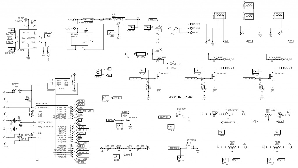
At first I just layed out the Atmega with its crystal and 2 caps. Then i thought I may as well add a voltage regulator and power cap as well.

Then I began to squeeze extras into the leftover board space. Before I knew it I had decided to create a board that had room for lots of peripherals but I wouldn’t necessarily populate the whole board if I didn’t need that function.

I had to choose what items to include and which were the best pins for them. I chose based on sensors and peripherals i had used and was comfortable with.

Some pins are fixed such as the I2C bus, the serial pins and the programming pins. The PWM pins I kept for the mosfets, and the analog pins for the sensors.

board

I tried to cram as much into the board as I could,trying to organize it into a usable pattern, while keeping everything as close as I dared. Somethings needed to be on the edge to be usable, and some things need to be reachable to the touch. In the end I did what I could and hoped it would be a useful PCB!

The board contains the following features!!

On board power regulator with a DC jack in, light dependant resistor, temperature thermistor, relay, piezo speaker, reset button, real time battery backed up clock,serial port, 2 buttons, 2 potentiometers, 2 LEDS, 2 servo ports, movement PIR sensor, 3 high power MosFets, 3 general purpose IO. All atmega pins and power supply pins are broken out to headers; power, mosfet and relay outputs are on screw terminal blocks. There is an ICSP programming header on board.

board on bag

I finished the schematic and layout of the board. I sent off the designs to the board house. The board has a few mistakes but on the whole I’m really happy with it.

The worst bodge is the battery holder which has the polarity back to front, I forgot that a button cell has the positive polarity on the outside of the case unlike normal cells. I was magically able to slide the cell holder over and solve the problem temporarily, so that was great. The mosfet jumper if used must be changed to a right angle though.

A lot of the polarities on the board are not marked, although a completed picture of the board makes assembly easy.

Board bodge

I paid for 10 boards at a little more than $2 each, then bought lots of parts at about $30 per board, so I could populate them. I decide to bag them all up individually and throw in a copy of the schematic and finished board picture with a few notes as well.

I thought I would give away a few kits to friends and throw a few up onto my blog shop for sale at the cost of parts only.
kits

The first thing i did when i got the boards, was put in the power system and check all the voltages, then i put the processor in with its crystal and caps. Then I uploaded a blink sketch and probed the led pin. After that all worked i just added parts one at a time testing each. I wrote a test sketch for all the functions. ,So far I have written code for a number of different tasks with it, including a clock, a thermostat relay, a movement sensitive night light, an RGB controller, and a dimmable led driver. There are many more things I will be using the board for in the future.bagged

If I run another batch of boards, I will fix the backup battery polarity, the labelling, change the back art, and maybe add an LCD header.

Here is the schematic, feel free to contact me for the board files and any code I have.

Here is my first test sketch..

/*

Arduino Dev board

20 July 2013

Toby Robb

This is a test sketch for the Arduino Development board
NOTES:

You must enable the internal pullups for the buttons by setting as inputs then writing HIGH
The leds if fitted also require the pullups to be enabled

*/

// Includes

#include <Servo.h> // Include the servo library

// Defines

#define ldrPin A2 // Light dependant resistor pin on board.
#define thermistorPin A3 //Temperature thermistor pin on board.
#define ledPin 8 // Led pin High for one colour Low for another
#define speakerPin 4 // The onboard speaker pin
#define relayPin 2 // Pin for the relay
#define sparePin 13 //Spare pin breakout on board

#define dataPin A4 // The I2C bus DATA pin
#define clockPin A5 // The I2C CLOCK pin

#define pot1Pin A0 // Number 1 potentiometer on the board.
#define pot2Pin A1 // Number 2 potentiometer on the board.

#define button1Pin 7 // Button 1 pin
#define button2Pin 12 // Button 2 pin

#define gpio1Pin 5 // General Purpose Input/output 1 pin
#define gpio2Pin 6 // General Purpose Input/output 2 pin
#define gpio3Pin 11 // General Purpose Input/output 3 pin

#define mosfet1Pin 3 // Mosfet 1 drive pin
#define mosfet2Pin 9 // Mosfet 2 drive pin
#define mosfet3Pin 10 // Mosfet 3 drive pin

Servo servo1; // create servo object to control a servo
// a maximum of eight servo objects can be created
int servoPos = 0; // variable to store the servo position

void setup(){

// Setup the serial

Serial.begin(9600);
Serial.println(“Beginning Setup”);

// Set up the pins

pinMode(ldrPin, INPUT); // If the light sensor resistor is fitted
pinMode(thermistorPin, INPUT); // If the temperature sensor resistor is fitted
pinMode(ledPin, OUTPUT); // You MUST use this if the LED’s are fitted.
pinMode(relayPin, OUTPUT); // If the relay is fitted.
pinMode(speakerPin, OUTPUT); // If the speaker is fitted.
pinMode(pot1Pin, INPUT); // If the potentiometer is fitted
pinMode(pot2Pin, INPUT); // If the potentiometer is fitted
pinMode(button1Pin, INPUT); // If the button is fitted (write HIGH to enable pullups)
pinMode(button2Pin, INPUT); // If the button is fitted (write HIGH to enable pullups)
pinMode(mosfet1Pin, OUTPUT); // Mosfet 1 output
pinMode(mosfet2Pin, OUTPUT); // Mosfet 2 output
pinMode(mosfet3Pin, OUTPUT); // Mosfet 3 output

servo1.attach(11); // attaches the servo on pin 11 gpio 3 to the servo object

// default states
digitalWrite(ledPin, HIGH);
digitalWrite(dataPin, HIGH);
digitalWrite(clockPin, HIGH);
digitalWrite(relayPin, LOW);
digitalWrite(button1Pin, HIGH); // enables pullups for buttons
digitalWrite(button2Pin, HIGH); // enables pullups for buttons

servo1.write(0);
}

void loop(){

//beep the buzzer
Serial.println(“Beep”);
tone(speakerPin, 500); // begin tone at 1000 hertz
delay(150); // wait half a sec
noTone(speakerPin); // end beep

//flash the leds
Serial.println(“Flash the LED’s”);
for(int i = 0; i<=8; i++){
digitalWrite(ledPin, HIGH); // turn the LED on (HIGH is the voltage level)
delay(100); // wait for a second
digitalWrite(ledPin, LOW); // turn the LED off by making the voltage LOW
delay(100); // wait for a second
}

// Cycle the relay
digitalWrite(relayPin, HIGH);
Serial.println(“Relay ON”);
delay(1000);
digitalWrite(relayPin, LOW);
Serial.println(“Relay OFF”);

// Test the mosfets

Serial.println(“Mosfet 1 blink”);
digitalWrite(mosfet1Pin, HIGH);
delay(250);
digitalWrite(mosfet1Pin, LOW);

Serial.println(“Mosfet 2 blink”);
digitalWrite(mosfet2Pin, HIGH);
delay(250);
digitalWrite(mosfet2Pin, LOW);

Serial.println(“Mosfet 3 blink”);
digitalWrite(mosfet3Pin, HIGH);
delay(250);
digitalWrite(mosfet3Pin, LOW);

// Sweep the servo on GPIO 3

Serial.println(“Sweep the servo”);
for(servoPos = 0; servoPos < 180; servoPos += 1) // goes from 0 degrees to 180 degrees
{ // in steps of 1 degree
servo1.write(servoPos); // tell servo to go to position in variable ‘servoPos’
delay(15); // waits 15ms for the servo to reach the position
}
for(servoPos = 180; servoPos>=1; servoPos-=1) // goes from 180 degrees to 0 degrees
{
servo1.write(servoPos); // tell servo to go to position in variable ‘servoPos’
delay(15); // waits 15ms for the servo to reach the position
}

// Print the value of the button states

Serial.print(“Button one state : “);
Serial.println(digitalRead(button1Pin));
Serial.print(“Button two state : “);
Serial.println(digitalRead(button2Pin));
delay(1000);

// Show the value of the LDR for a few seconds
for(int i = 0; i <=50; i++){
Serial.print(“The brightness : “);
Serial.println(analogRead(ldrPin));
}

//show the value of the temperature thermistor for a few seconds
for(int i = 0; i <=50; i++){
Serial.print(“The Temperature : “);
Serial.println(analogRead(thermistorPin));
}

// Print off the potentiometer value for a few seconds
for(int i = 0; i <=50; i++){
Serial.print(“Potentiometer one : “);
Serial.println(analogRead(pot1Pin));
}
for(int i = 0; i <=50; i++){
Serial.print(“Potentiometer two : “);
Serial.println(analogRead(pot2Pin));
}

delay(3000);

}

Night Light Sensor widget

Over the last few months I have been putting some effort into prototyping my first printed circuit board. For me the process went better than I could have expected.

For me it really started when I built my first day/night light. I used a light dependant resistor to determine if it was dark and if it was to then turn on an LED light.

I then went on to add a movement sensor. From there I built a multi channel lighting controller. With very small thin low voltage wires running all over the place, hot glued in spots to the walls and floors. I can’t tell you how nice it is to have automated lighting. It seems like such a simple thing to go over and turn on a light switch, but believe me after having an automated system, If I go somewhere else to another house or hotel I realize how luxurious and satisfying it is not to have to turn the switches on and off in order as I move from room to room.

So what started out as a simple test of coding and sensors and logic, has seen me refine the design iteration by iteration. Not really in terms of capability but more in the way the parts come together and the way it is used. In terms of the hardware I have gone from breadboard, to prototyping board and soldered parts, to a fully custom printed circuit board (PCB). In the way of usability I have gone from very messy blobs of electronics laying on the floor, to an encased multi channel box, but with wires everywhere, then to a single board per light solution, with onboard adjustable dials.

After hearing and watching Dave Jones from the (http://www.eevblog.com) talk about PCB layout and the possibility of getting my boards made for under $20 for 10 delivered to my door, I really want to have a go at it. Now the first time I tried using the program without watching some tutorials I wasn’t really able to achieve much. But then I decided to use Youtube to my advantage. Yes its not just for cute cat videos. rpcelectronics have a seriously good quick set of videos to follow along to with your own free copy of eagle cad.

Itead Studios is where you can get your self some great 2 layer coloured PCB’s. Just send them your exported files from eagle cad and they will send you your boards in about 4 weeks or so.

So what’s next:-

A change to the on/off jumper to allow for AC.
A new revision of the board, possibly smaller with some smaller surface mounted parts.
Some changes to labelling.
A reset button.
ICSP (In Circuit Serial Programming).
Clean up the code and make possible improvements.

And of course I am posting my code. I am not a programmer by any means.

/*
Day night IR sensor shield 11/08/12 Trobb

DEBUG VERSION!!!!

*/

#include <avr/wdt.h>

#define ldr A0 // LDR light sensor
#define ir A1 // IR movement sensor pin
#define timerPot A2 // Pin the timer potentiometer is connected to

#define watchdogPin 3 // Uncomment this line to have a pin blink to let us know the code is running

#define led 3 // Output for LED

#define gain 10 // the amount of gain to add to the timerPot 10 is a normal value
int luxVal = 500; // Value to trigger the low light condition
float timerValue; // A variable to hold the value of the delay on time
float timerDelay;


void setup() {

// initialize the IO.

// pinMode(watchdogPin, OUTPUT); // Uncomment this line to have a different pin blink to let us know the code is running

pinMode(led, OUTPUT);
pinMode(ir, INPUT);
pinMode(ldr, INPUT);
digitalWrite(led, LOW); // start with LED off

Serial.begin(9600);

wdt_reset(); //make sure we reset watchdog timer to prevent endless resetting

// Uncomment this section to have a pin blink to let us know the code is running
// blink some morse code OK

digitalWrite(watchdogPin, HIGH); // blink watchdog led
delay(500);
digitalWrite(watchdogPin, LOW);
delay(500);
digitalWrite(watchdogPin, HIGH); // blink watchdog led
delay(500);
digitalWrite(watchdogPin, LOW);
delay(500);
digitalWrite(watchdogPin, HIGH); // blink watchdog led
delay(500);
digitalWrite(watchdogPin, LOW);
delay(1500);
digitalWrite(watchdogPin, HIGH); // blink watchdog led
delay(500);
digitalWrite(watchdogPin, LOW);
delay(500);
digitalWrite(watchdogPin, HIGH); // blink watchdog led
delay(250);
digitalWrite(watchdogPin, LOW);
delay(500);
digitalWrite(watchdogPin, HIGH); // blink watchdog led
delay(500);
digitalWrite(watchdogPin, LOW);


Serial.println(“Setup complete”);
}

void loop() {

wdt_reset(); //make sure we reset watchdog timer to prevent endless resetting

// Lets print some debugging values to the console

Serial.print(“Current ldr reading is “);
Serial.println(analogRead(ldr));
Serial.print(“Current sensor value “);
Serial.println(digitalRead(ir));
Serial.print(“Current timer value is “);
Serial.println(analogRead(timerPot));

wdt_reset(); //make sure we reset watchdog timer to prevent endless resetting


// Now check for darkness or daylight and movement

// so long as its dark

while(analogRead(ldr)<=luxVal){

Serial.println(“Its dark”);

// and movement is detected
if(digitalRead(ir) == 1){
Serial.println(“Movement detected”);
digitalWrite(led, HIGH); // turn led on
Serial.println(“LED is ON”);

// now leave light on for a predetermined time

timerValue = analogRead(timerPot);
timerDelay = timerValue * (timerValue / gain); // times the value by itself divided by gain

Serial.println(timerDelay);

float i = timerDelay; // set timer variable
while(i >=0){
i -;
Serial.print(“Timing out “);
Serial.println(i);

wdt_reset(); //make sure we reset watchdog timer within the loop to prevent endless resetting
}
}

else{
Serial.println(“No movement”); // no movement detected so turn led off
digitalWrite(led, LOW); // turn led off
wdt_reset(); //make sure we reset watchdog timer to prevent endless resetting
}

}
// not dark enough yet

Serial.println(“still not dark enough”);

digitalWrite(led, LOW); // turn led off
wdt_reset(); //make sure we reset watchdog timer to prevent endless resetting
}

LED Night Sensor Widget Assembly Notes.

Toby Robb 2013

This board can be fed from either AC or DC 7-35 Volts. 7-9 volts DC is ideal as it generates less heat in the regulator.

With heatsinking the regulator can probably safely deliver up to 750mA.

The output at the terminals is 5 Volts. Calculate your LED load resistor accordingly.

With a 3 Watt led everything runs quite hot especially the load resistor, the regulator and the LED itself. So care must
be taken when siting the board to avoid anything catching fire. You have been warned!

A 1 Watt led is ideal for this board.

There are a couple of mistakes in the board at the moment.

The 2 Power capacitors are marked incorrectly on the board. They need to swap positions.
The larger electrolytic should be on the DC regulated side.

The LDR fixed resistor should be a solid link.

Choose your load resistor to suit your LED. Keep the current below 750mA, or even lower if you can.

The values printed on the board for the brightness and delay potentiometers are marked
incorrectly on the board. They need to swap positions.
Note: The jumper will probably not cut the power if your using AC in. If you are using DC
the screw on the left should be positive and the jumper will work.

Known bugs: If you face the light back to into the LDR you may get oscillations.
The light will switch on and off a few times as it aproaches darkness. This needs a proper
fix in software.


Here below is a possible revision to the code I have been working on.
/*
Day night IR sensor shield 11/08/12 Trobb

Please enjoy my dodgy code!

I am not a programmer by any means!

Feel free to improve on it!

Check out http://www.tobyrobb.com

Written with Arduino IDE V.1.0.1

DEBUG VERSION!!!!

*/

#include <avr/wdt.h>

#define ldr A0 // LDR light sensor
#define ir A1 // IR movement sensor pin
#define timerPot A2 // Pin the timer potentiometer is connected to

#define watchdogPin 3 // Uncomment this line to have a pin blink to let us know the code is running

#define led 3 // Output for LED

#define gain 10 // the amount of gain to add to the timerPot 10 is a normal value
int luxVal = 150; // Value to trigger the low light condition
float timerValue; // A variable to hold the value of the delay on time
float timerDelay;
int dark = 0;
long previousMillis = 0; // will store last time LED was updated

// the follow variables is a long because the time, measured in miliseconds,
// will quickly become a bigger number than can be stored in an int.
long interval = 1000; // interval at which to check the LDR (milliseconds)


void setup() {

// initialize the IO.

// pinMode(watchdogPin, OUTPUT); // Uncomment this line to have a different pin blink to let us know the code is running

pinMode(led, OUTPUT);
pinMode(ir, INPUT);
pinMode(ldr, INPUT);
digitalWrite(led, LOW); // start with LED off

Serial.begin(9600);

wdt_reset(); //make sure we reset watchdog timer to prevent endless resetting

// Uncomment this section to have a pin blink to let us know the code is running
// blink some morse code OK

digitalWrite(watchdogPin, HIGH); // blink watchdog led
delay(500);
digitalWrite(watchdogPin, LOW);
delay(500);
digitalWrite(watchdogPin, HIGH); // blink watchdog led
delay(500);
digitalWrite(watchdogPin, LOW);
delay(500);
digitalWrite(watchdogPin, HIGH); // blink watchdog led
delay(500);
digitalWrite(watchdogPin, LOW);
delay(1500);
digitalWrite(watchdogPin, HIGH); // blink watchdog led
delay(500);
digitalWrite(watchdogPin, LOW);
delay(500);
digitalWrite(watchdogPin, HIGH); // blink watchdog led
delay(250);
digitalWrite(watchdogPin, LOW);
delay(500);
digitalWrite(watchdogPin, HIGH); // blink watchdog led
delay(500);
digitalWrite(watchdogPin, LOW);


Serial.println(“Setup complete”);
}

void loop() {

wdt_reset(); //make sure we reset watchdog timer to prevent endless resetting

// Lets print some debugging values to the console

Serial.print(“Current ldr reading is “);
Serial.println(analogRead(ldr));
Serial.print(“Current sensor value “);
Serial.println(digitalRead(ir));
Serial.print(“Current timer value is “);
Serial.println(analogRead(timerPot));
wdt_reset(); //make sure we reset watchdog timer to prevent endless resetting

// Now check for darkness or daylight and movement

checkLdr();

// so long as its dark

while(dark <=0){

Serial.println(“Its dark”);

// and movement is detected
if(digitalRead(ir) == 1){
Serial.println(“Movement detected”);
digitalWrite(led, HIGH); // turn led on
Serial.println(“LED is ON”);

// now leave light on for a predetermined time

timerValue = analogRead(timerPot);
timerDelay = timerValue * (timerValue / gain); // times the value by itself divided by gain

Serial.println(timerDelay);

float i = timerDelay; // set timer variable
while(i >=0){
i -;
Serial.print(“Timing out “);
Serial.println(i);
checkLdr();
if(dark<=0){
return;
}
wdt_reset(); //make sure we reset watchdog timer within the loop to prevent endless resetting
}
}

else{
Serial.println(“No movement”); // no movement detected so turn led off
digitalWrite(led, LOW); // turn led off
checkLdr();
wdt_reset(); //make sure we reset watchdog timer to prevent endless resetting
}

}
// not dark enough yet

Serial.println(“still not dark enough”);

digitalWrite(led, LOW); // turn led off
wdt_reset(); //make sure we reset watchdog timer to prevent endless resetting
}


void checkLdr(){

// check to see if it’s time to read the LDR;

// difference between the current time and last time

unsigned long currentMillis = millis();

if(currentMillis - previousMillis > interval) {
// save the last time you checked the LDR
previousMillis = currentMillis;

Serial.println(“Checking LDR”);

if(analogRead(ldr)>=luxVal){

dark++;

}
if(analogRead(ldr)<=luxVal){

dark-;

}
if(dark>=5){
dark = 5;

}
if(dark <=-5){
dark = -5;
}
}
Serial.print(“Current dark reading is “);
Serial.println(dark);
}