Morse code keyer for Arduino.
I recently decided to build another project, this time involving morse code and the arduino.
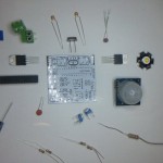
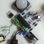
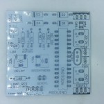
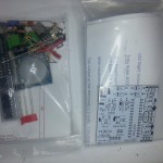
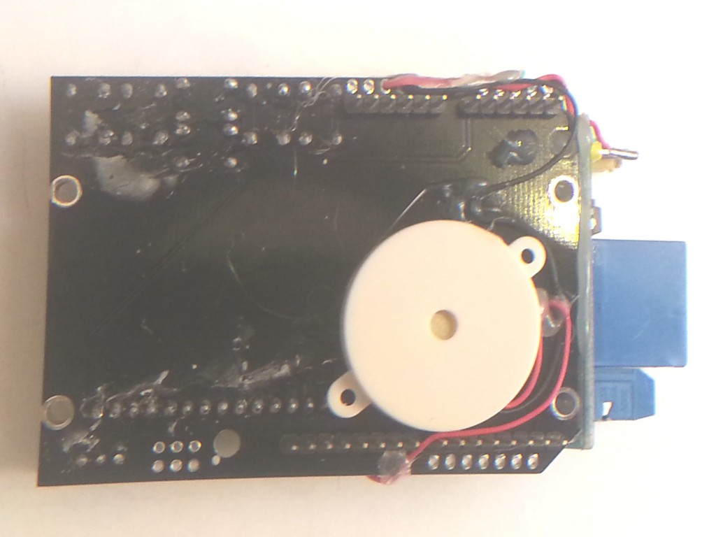
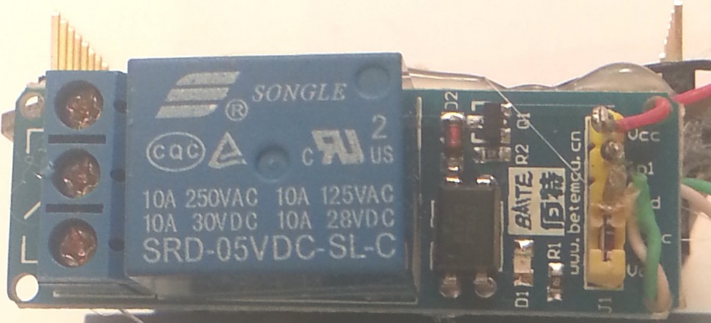
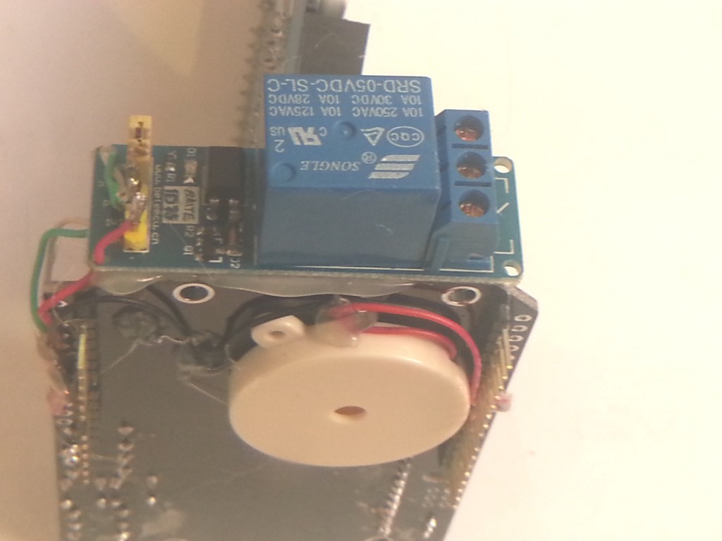
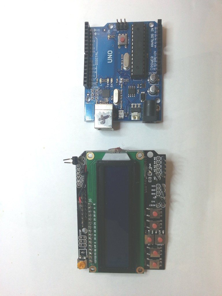
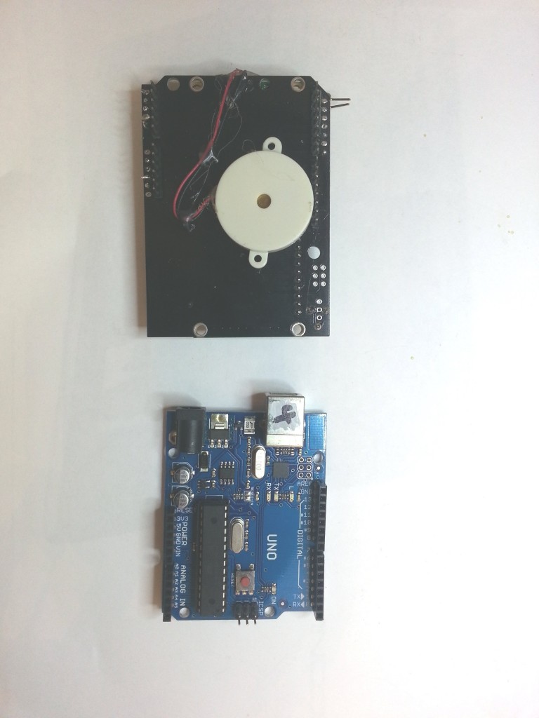
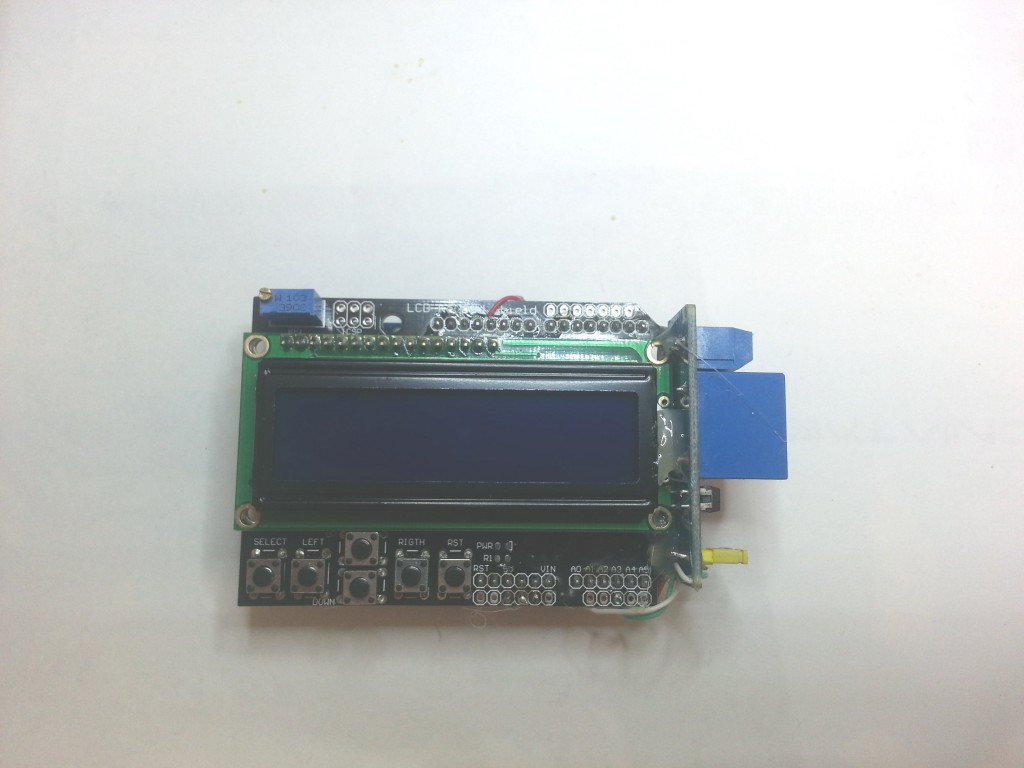
I took a standard Arduino UNO, an LCD keypad shield, a relay module and a piezo buzzer. Total cost was under $25
What does it do?
Well it can send morse cq’s or any morse message to the onboard piezo or the relay for connection across a radio key. It has the ability to adjust the speed and timing of the morse. It demo’s the morse alphabet. You can decide it you want to use the relay or not. It can save the settings to the onboard EEPROM and keep them on power off.
The code was a little complicated to write, but it was my first attempt at a menu system. Initially i imagined a grid system of menus using up/down/left/right. Each row would represent a type of function and the pages along the row each related to each other. This meant holding a variable for the column number, a variable for row number, both of which to be looped around or limited. I would then also need to keep a number at the intersection of the row and column which would be the page number. Phew, 3 variables just to start with. I did manage to get it working but wondered if there was a smarter way to go about it.
I believe in trying to do it your self, so you can learn first. Once you’ve tried it your way, head over to the web and see how the programmers do it! I decided to look around the web.
One example i saw, had left or right scrolling through all of the functions, looping back around to the start. One variable, the program number, incremented or decremented by the left and right keys. Much smarter,simpler and good enough for what i was trying to do here, keep it simple for me and if anyone else wanted to use it.
So that’s pretty much how the code goes.
I browsed around the web trying to improve my programming skills, as this was probably the hardest code I had written to date. I learned somewhere along the way that good practice was to write out all your comments first, then fill the code in later.
For example;
// here is where the setup will be
// here is where we will define all the variables
// This is the routine that converts a letter into dits and dahs
// this is where the menu code will live
And so on. I added a notes section that described the programs way of working. And i added a TO DO list, for example;
TODO:
add press any key to abort
change pitch of morse key sound
add numbers and special characters
maybe reduce system to one key, short press advances menu, long press to use
provide ability to enter a custom message ie callsign direct from the keypad
beacon menu support
serial control or ethernet if possible
special sounds? psk replies??
A todo list was something that i later found to be an invaluable way of adding things that needed to be fixed.
There have been ten revisions so far, each one adding more capability to the device, I hope the code can be improved further still. There’s even a bit of silly stuff thrown in there for fun.
/*
T Robb 12 sep 12
just a dodgy bit of code, that ought to let you play morse through a speaker or a relay
$ver 0.40
NOTES:
it waits to see if a key has been pressed, if so it increments or decrements the programnumber.
then it compares the programnumber against a number: switch(programnumber)
and runs the appropriate menu
all the functions are at the bottom
there are functions for each letter
there are generally functions for each menu
you may need to put delays in between each letter
TODO:
press any key to abort
change pitch of morse key sound
relay on or off
add numbers and special characters
maybe reduce system to one key
add saving of the variables to non volatile ram
provide ability to enter a custom message ie callsign
beacon support
serial control or ethernet if possible
special sounds? psk replies??
*/
/*************************************************
* Get the notes and stuff just for the music out of the way first. the music is not really important , just a gimmick really
*************************************************/
#define NOTE_B0 31
#define NOTE_C1 33
#define NOTE_CS1 35
#define NOTE_D1 37
#define NOTE_DS1 39
#define NOTE_E1 41
#define NOTE_F1 44
#define NOTE_FS1 46
#define NOTE_G1 49
#define NOTE_GS1 52
#define NOTE_A1 55
#define NOTE_AS1 58
#define NOTE_B1 62
#define NOTE_C2 65
#define NOTE_CS2 69
#define NOTE_D2 73
#define NOTE_DS2 78
#define NOTE_E2 82
#define NOTE_F2 87
#define NOTE_FS2 93
#define NOTE_G2 98
#define NOTE_GS2 104
#define NOTE_A2 110
#define NOTE_AS2 117
#define NOTE_B2 123
#define NOTE_C3 131
#define NOTE_CS3 139
#define NOTE_D3 147
#define NOTE_DS3 156
#define NOTE_E3 165
#define NOTE_F3 175
#define NOTE_FS3 185
#define NOTE_G3 196
#define NOTE_GS3 208
#define NOTE_A3 220
#define NOTE_AS3 233
#define NOTE_B3 247
#define NOTE_C4 262
#define NOTE_CS4 277
#define NOTE_D4 294
#define NOTE_DS4 311
#define NOTE_E4 330
#define NOTE_F4 349
#define NOTE_FS4 370
#define NOTE_G4 392
#define NOTE_GS4 415
#define NOTE_A4 440
#define NOTE_AS4 466
#define NOTE_B4 494
#define NOTE_C5 523
#define NOTE_CS5 554
#define NOTE_D5 587
#define NOTE_DS5 622
#define NOTE_E5 659
#define NOTE_F5 698
#define NOTE_FS5 740
#define NOTE_G5 784
#define NOTE_GS5 831
#define NOTE_A5 880
#define NOTE_AS5 932
#define NOTE_B5 988
#define NOTE_C6 1047
#define NOTE_CS6 1109
#define NOTE_D6 1175
#define NOTE_DS6 1245
#define NOTE_E6 1319
#define NOTE_F6 1397
#define NOTE_FS6 1480
#define NOTE_G6 1568
#define NOTE_GS6 1661
#define NOTE_A6 1760
#define NOTE_AS6 1865
#define NOTE_B6 1976
#define NOTE_C7 2093
#define NOTE_CS7 2217
#define NOTE_D7 2349
#define NOTE_DS7 2489
#define NOTE_E7 2637
#define NOTE_F7 2794
#define NOTE_FS7 2960
#define NOTE_G7 3136
#define NOTE_GS7 3322
#define NOTE_A7 3520
#define NOTE_AS7 3729
#define NOTE_B7 3951
#define NOTE_C8 4186
#define NOTE_CS8 4435
#define NOTE_D8 4699
#define NOTE_DS8 4978
#define OCTAVE_OFFSET 0
int notes[] = { 0,
NOTE_C4, NOTE_CS4, NOTE_D4, NOTE_DS4, NOTE_E4, NOTE_F4, NOTE_FS4, NOTE_G4, NOTE_GS4, NOTE_A4, NOTE_AS4, NOTE_B4,
NOTE_C5, NOTE_CS5, NOTE_D5, NOTE_DS5, NOTE_E5, NOTE_F5, NOTE_FS5, NOTE_G5, NOTE_GS5, NOTE_A5, NOTE_AS5, NOTE_B5,
NOTE_C6, NOTE_CS6, NOTE_D6, NOTE_DS6, NOTE_E6, NOTE_F6, NOTE_FS6, NOTE_G6, NOTE_GS6, NOTE_A6, NOTE_AS6, NOTE_B6,
NOTE_C7, NOTE_CS7, NOTE_D7, NOTE_DS7, NOTE_E7, NOTE_F7, NOTE_FS7, NOTE_G7, NOTE_GS7, NOTE_A7, NOTE_AS7, NOTE_B7
};
// we can choose a song here, its placing the notes in a character array which is being referenced in the menu
char *song1 = “The Simpsons:d=4,o=5,b=160:c.6,e6,f#6,8a6,g.6,e6,c6,8a,8f#,8f#,8f#,2g,8p,8p,8f#,8f#,8f#,8g,a#.,8c6,8c6,8c6,c6″;
//char *song = “Indiana:d=4,o=5,b=250:e,8p,8f,8g,8p,1c6,8p.,d,8p,8e,1f,p.,g,8p,8a,8b,8p,1f6,p,a,8p,8b,2c6,2d6,2e6,e,8p,8f,8g,8p,1c6,p,d6,8p,8e6,1f.6,g,8p,8g,e.6,8p,d6,8p,8g,e.6,8p,d6,8p,8g,f.6,8p,e6,8p,8d6,2c6″;
//char *song = “TakeOnMe:d=4,o=4,b=160:8f#5,8f#5,8f#5,8d5,8p,8b,8p,8e5,8p,8e5,8p,8e5,8g#5,8g#5,8a5,8b5,8a5,8a5,8a5,8e5,8p,8d5,8p,8f#5,8p,8f#5,8p,8f#5,8e5,8e5,8f#5,8e5,8f#5,8f#5,8f#5,8d5,8p,8b,8p,8e5,8p,8e5,8p,8e5,8g#5,8g#5,8a5,8b5,8a5,8a5,8a5,8e5,8p,8d5,8p,8f#5,8p,8f#5,8p,8f#5,8e5,8e5″;
//char *song = “Entertainer:d=4,o=5,b=140:8d,8d#,8e,c6,8e,c6,8e,2c.6,8c6,8d6,8d#6,8e6,8c6,8d6,e6,8b,d6,2c6,p,8d,8d#,8e,c6,8e,c6,8e,2c.6,8p,8a,8g,8f#,8a,8c6,e6,8d6,8c6,8a,2d6″;
//char *song = “Muppets:d=4,o=5,b=250:c6,c6,a,b,8a,b,g,p,c6,c6,a,8b,8a,8p,g.,p,e,e,g,f,8e,f,8c6,8c,8d,e,8e,8e,8p,8e,g,2p,c6,c6,a,b,8a,b,g,p,c6,c6,a,8b,a,g.,p,e,e,g,f,8e,f,8c6,8c,8d,e,8e,d,8d,c”;
//char *song = “Xfiles:d=4,o=5,b=125:e,b,a,b,d6,2b.,1p,e,b,a,b,e6,2b.,1p,g6,f#6,e6,d6,e6,2b.,1p,g6,f#6,e6,d6,f#6,2b.,1p,e,b,a,b,d6,2b.,1p,e,b,a,b,e6,2b.,1p,e6,2b.”;
//char *song = “Looney:d=4,o=5,b=140:32p,c6,8f6,8e6,8d6,8c6,a.,8c6,8f6,8e6,8d6,8d#6,e.6,8e6,8e6,8c6,8d6,8c6,8e6,8c6,8d6,8a,8c6,8g,8a#,8a,8f”;
//char *song = “20thCenFox:d=16,o=5,b=140:b,8p,b,b,2b,p,c6,32p,b,32p,c6,32p,b,32p,c6,32p,b,8p,b,b,b,32p,b,32p,b,32p,b,32p,b,32p,b,32p,b,32p,g#,32p,a,32p,b,8p,b,b,2b,4p,8e,8g#,8b,1c#6,8f#,8a,8c#6,1e6,8a,8c#6,8e6,1e6,8b,8g#,8a,2b”;
//char *song = “Bond:d=4,o=5,b=80:32p,16c#6,32d#6,32d#6,16d#6,8d#6,16c#6,16c#6,16c#6,16c#6,32e6,32e6,16e6,8e6,16d#6,16d#6,16d#6,16c#6,32d#6,32d#6,16d#6,8d#6,16c#6,16c#6,16c#6,16c#6,32e6,32e6,16e6,8e6,16d#6,16d6,16c#6,16c#7,c.7,16g#6,16f#6,g#.6″;
//char *song = “MASH:d=8,o=5,b=140:4a,4g,f#,g,p,f#,p,g,p,f#,p,2e.,p,f#,e,4f#,e,f#,p,e,p,4d.,p,f#,4e,d,e,p,d,p,e,p,d,p,2c#.,p,d,c#,4d,c#,d,p,e,p,4f#,p,a,p,4b,a,b,p,a,p,b,p,2a.,4p,a,b,a,4b,a,b,p,2a.,a,4f#,a,b,p,d6,p,4e.6,d6,b,p,a,p,2b”;
//char *song = “StarWars:d=4,o=5,b=45:32p,32f#,32f#,32f#,8b.,8f#.6,32e6,32d#6,32c#6,8b.6,16f#.6,32e6,32d#6,32c#6,8b.6,16f#.6,32e6,32d#6,32e6,8c#.6,32f#,32f#,32f#,8b.,8f#.6,32e6,32d#6,32c#6,8b.6,16f#.6,32e6,32d#6,32c#6,8b.6,16f#.6,32e6,32d#6,32e6,8c#6″;
//char *song = “GoodBad:d=4,o=5,b=56:32p,32a#,32d#6,32a#,32d#6,8a#.,16f#.,16g#.,d#,32a#,32d#6,32a#,32d#6,8a#.,16f#.,16g#.,c#6,32a#,32d#6,32a#,32d#6,8a#.,16f#.,32f.,32d#.,c#,32a#,32d#6,32a#,32d#6,8a#.,16g#.,d#”;
//char *song = “TopGun:d=4,o=4,b=31:32p,16c#,16g#,16g#,32f#,32f,32f#,32f,16d#,16d#,32c#,32d#,16f,32d#,32f,16f#,32f,32c#,16f,d#,16c#,16g#,16g#,32f#,32f,32f#,32f,16d#,16d#,32c#,32d#,16f,32d#,32f,16f#,32f,32c#,g#”;
//char *song = “A-Team:d=8,o=5,b=125:4d#6,a#,2d#6,16p,g#,4a#,4d#.,p,16g,16a#,d#6,a#,f6,2d#6,16p,c#.6,16c6,16a#,g#.,2a#”;
//char *song = “Flinstones:d=4,o=5,b=40:32p,16f6,16a#,16a#6,32g6,16f6,16a#.,16f6,32d#6,32d6,32d6,32d#6,32f6,16a#,16c6,d6,16f6,16a#.,16a#6,32g6,16f6,16a#.,32f6,32f6,32d#6,32d6,32d6,32d#6,32f6,16a#,16c6,a#,16a6,16d.6,16a#6,32a6,32a6,32g6,32f#6,32a6,8g6,16g6,16c.6,32a6,32a6,32g6,32g6,32f6,32e6,32g6,8f6,16f6,16a#.,16a#6,32g6,16f6,16a#.,16f6,32d#6,32d6,32d6,32d#6,32f6,16a#,16c.6,32d6,32d#6,32f6,16a#,16c.6,32d6,32d#6,32f6,16a#6,16c7,8a#.6″;
//char *song = “Jeopardy:d=4,o=6,b=125:c,f,c,f5,c,f,2c,c,f,c,f,a.,8g,8f,8e,8d,8c#,c,f,c,f5,c,f,2c,f.,8d,c,a#5,a5,g5,f5,p,d#,g#,d#,g#5,d#,g#,2d#,d#,g#,d#,g#,c.7,8a#,8g#,8g,8f,8e,d#,g#,d#,g#5,d#,g#,2d#,g#.,8f,d#,c#,c,p,a#5,p,g#.5,d#,g#”;
char *song2 = “Gadget:d=16,o=5,b=50:32d#,32f,32f#,32g#,a#,f#,a,f,g#,f#,32d#,32f,32f#,32g#,a#,d#6,4d6,32d#,32f,32f#,32g#,a#,f#,a,f,g#,f#,8d#”;
//char *song = “Smurfs:d=32,o=5,b=200:4c#6,16p,4f#6,p,16c#6,p,8d#6,p,8b,p,4g#,16p,4c#6,p,16a#,p,8f#,p,8a#,p,4g#,4p,g#,p,a#,p,b,p,c6,p,4c#6,16p,4f#6,p,16c#6,p,8d#6,p,8b,p,4g#,16p,4c#6,p,16a#,p,8b,p,8f,p,4f#”;
//char *song = “MahnaMahna:d=16,o=6,b=125:c#,c.,b5,8a#.5,8f.,4g#,a#,g.,4d#,8p,c#,c.,b5,8a#.5,8f.,g#.,8a#.,4g,8p,c#,c.,b5,8a#.5,8f.,4g#,f,g.,8d#.,f,g.,8d#.,f,8g,8d#.,f,8g,d#,8c,a#5,8d#.,8d#.,4d#,8d#.”;
//char *song = “LeisureSuit:d=16,o=6,b=56:f.5,f#.5,g.5,g#5,32a#5,f5,g#.5,a#.5,32f5,g#5,32a#5,g#5,8c#.,a#5,32c#,a5,a#.5,c#.,32a5,a#5,32c#,d#,8e,c#.,f.,f.,f.,f.,f,32e,d#,8d,a#.5,e,32f,e,32f,c#,d#.,c#”;
//char *song = “MissionImp:d=16,o=6,b=95:32d,32d#,32d,32d#,32d,32d#,32d,32d#,32d,32d,32d#,32e,32f,32f#,32g,g,8p,g,8p,a#,p,c7,p,g,8p,g,8p,f,p,f#,p,g,8p,g,8p,a#,p,c7,p,g,8p,g,8p,f,p,f#,p,a#,g,2d,32p,a#,g,2c#,32p,a#,g,2c,a#5,8c,2p,32p,a#5,g5,2f#,32p,a#5,g5,2f,32p,a#5,g5,2e,d#,8d”;
// include the library code:
#include <LiquidCrystal.h> // The library for the LCD display
#include <EEPROM.h> // the library for writing to and from the EEPROM
// initialize the LCD library with the numbers of the interface pins
// pin 10 is revserved for backlight pin on my lcd keypad, so remember not to use that for anything else
LiquidCrystal lcd(8, 9, 4, 5, 6, 7);
int buttonPin = A0; // The button pin on my keypad
int speakerPin = 11; // The spare pin i have chosen to drive a piezo speaker
int relayPin = A3; // The pin i have chosen to drive the relay. 40ma is recommended max, in practice you may get a little higher.
// define all the morse lengths and pitch here.
int key = 700; // pitch of the morse key 900hz?
int dit = 400; // length of a dit in milliseconds
int dah = 1300; // length of a dit in milliseconds
int space_dahdits = 150; // space between dots and dashes
int space_char = 380; // space between letters (may not be used)
int space_word = 1140; // space between words (may not be used)
int relayCase = 0; // toggle the choice of wether we want the relay to be used
int maxprogramnumber = 16; // dont forget to increase the menu numbers here!!
int programnumber = 1;
// this is where the main routine runs
void setup() {
Serial.begin(9600);
pinMode(buttonPin, INPUT);
pinMode(relayPin, OUTPUT);
digitalWrite(relayPin, HIGH); // the relay is a low to turn on so we keep it high at the start
// set up the LCD’s number of columns and rows:
lcd.begin(16, 2);
tone(speakerPin, 900, 75);
lcd.clear();
lcd.setCursor(0, 0);
lcd.print(” T.Robb V0.46 “); //Print a little message
lcd.setCursor(0, 1);
lcd.print(“Long Live Morse! “);
delay(1500);
readEeprom(); // this is where we read in the eeprom values
menu();
}
void loop() {
}
void menu(){
Serial.println(programnumber);
Serial.println(analogRead(14));
Serial.println(relayCase);
switch(programnumber){
// This is where you add or remove menu items and changs the menu names
// dont forget to increase the menu numbers at the bottom
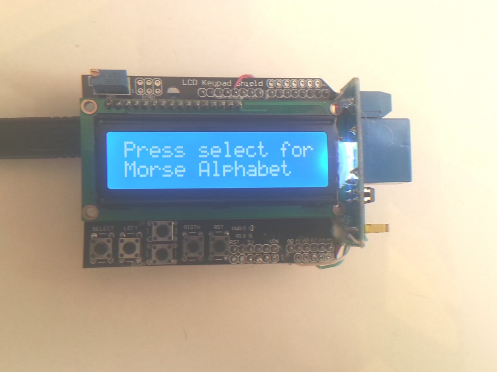
case 1:
lcd.setCursor(0, 0);
lcd.print(“Press select for.”);
lcd.setCursor(0, 1);
lcd.print(“Morse Alphabet “);
break;
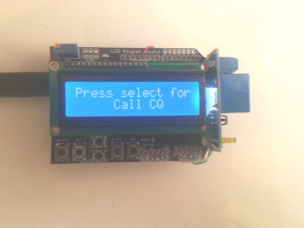
case 2:
lcd.setCursor(0, 0);
lcd.print(“Press select for.”);
lcd.setCursor(0, 1);
lcd.print(” Call CQ “);
break;
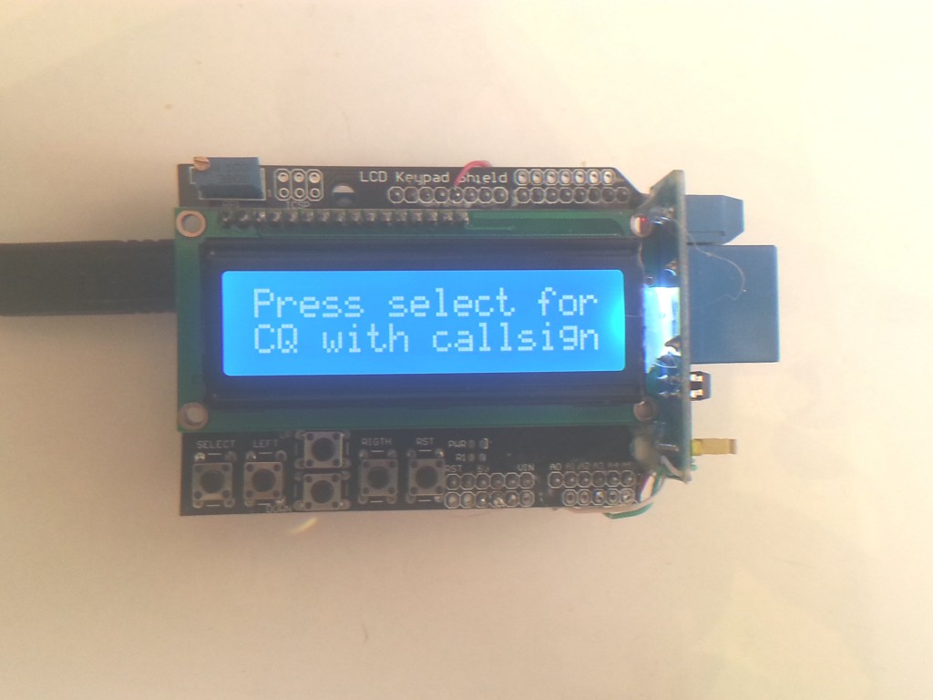
case 3:
lcd.setCursor(0, 0);
lcd.print(“Press select for.”);
lcd.setCursor(0, 1);
lcd.print(“CQ with callsign”);
break;
case 4:
lcd.setCursor(0, 0);
lcd.print(“Press select for.”);
lcd.setCursor(0, 1);
lcd.print(“Play Callsign “);
break;
case 5:
lcd.setCursor(0, 0);
lcd.print(“Press select for.”);
lcd.setCursor(0, 1);
lcd.print(“This is callsign”);
break;
case 6:
lcd.setCursor(0, 0);
lcd.print(“Press select for.”);
lcd.setCursor(0, 1);
lcd.print(“The Simpsons?? “);
break;
case 7:
lcd.setCursor(0, 0);
lcd.print(“Press select for.”);
lcd.setCursor(0, 1);
lcd.print(“Inspector Gadget”);
break;
case 8:
lcd.setCursor(0, 0);
lcd.print(“Press select for.”);
lcd.setCursor(0, 1);
lcd.print(“Increase speed +”);
break;
case 9:
lcd.setCursor(0, 0);
lcd.print(“Press select for.”);
lcd.setCursor(0, 1);
lcd.print(“Decrease speed -”);
break;
case 10:
lcd.setCursor(0, 0);
lcd.print(“Press select for.”);
lcd.setCursor(0, 1);
lcd.print(“Space length +”);
break;
case 11:
lcd.setCursor(0, 0);
lcd.print(“Press select for.”);
lcd.setCursor(0, 1);
lcd.print(“Space length -”);
break;
case 12:
lcd.setCursor(0, 0);
lcd.print(“Press select for.”);
lcd.setCursor(0, 1);
lcd.print(“Increase pitch +”);
break;
case 13:
lcd.setCursor(0, 0);
lcd.print(“Press select for.”);
lcd.setCursor(0, 1);
lcd.print(“Decrease pitch -”);
break;
case 14:
lcd.setCursor(0, 0);
lcd.print(“Press select for.”);
lcd.setCursor(0, 1);
lcd.print(” Toggle Relay “);
break;
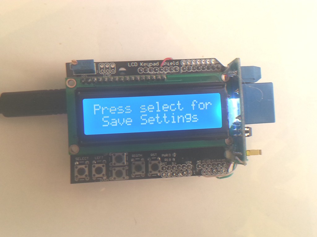
case 15:
lcd.setCursor(0, 0);
lcd.print(“Press select for.”);
lcd.setCursor(0, 1);
lcd.print(” Save Settings “);
break;
case 16:
lcd.setCursor(0, 0);
lcd.print(“Press select for.”);
lcd.setCursor(0, 1);
lcd.print(“Default Settings”);
break;
default:
lcd.setCursor(0, 0);
lcd.print(“Press select for.”);
lcd.setCursor(0, 1);
lcd.print(“Plays Callsign “);
break;
}
// dont forget to increment maxprogramnumber at the top of file
while((analogRead(buttonPin))>=1000){} // do nothing while no buttons pressed to chill out
delay(5);
if((analogRead(buttonPin))<=50){
programnumber++;
delay(300);
}
if(analogRead(buttonPin)>=100 && analogRead(buttonPin)<=200){
programnumber-;
delay(30);
}
if(analogRead(buttonPin)>=200 && analogRead(buttonPin)<=400){
programnumber++;
delay(10);
}
if(analogRead(buttonPin)>=400 && analogRead(buttonPin)<=600){
programnumber-;
delay(300);
}
if(programnumber > maxprogramnumber){programnumber = 1;} // this is where the menu goes around and around
if(programnumber < 1){programnumber = maxprogramnumber;}
if(analogRead(buttonPin)>=600 && analogRead(buttonPin)<=800){
Serial.println(“Button Pressed”);
switch(programnumber){
case 1:
Serial.println(“alphabet”);
alphabet();
break;
case 2:
Serial.println(“play 1″);
cq();
cq();
cq();
break;
case 3:
Serial.println(“play 3″);
cqCallsign();
break;
case 4:
Serial.println(“play 2″);
callsign();
break;
case 5:
Serial.println(“play 4″);
thisIs();
break;
case 6:
Serial.println(“play 5″);
play_rtttl(song1);
break;
case 7:
Serial.println(“play 5″);
play_rtttl(song2);
break;
case 8:
Serial.println(“speed up”);
faster();
break;
case 9:
Serial.println(“slow down”);
slower();
break;
case 10:
Serial.println(“space length increase”);
spaceLonger();
break;
case 11:
Serial.println(“space length decrease”);
spaceShorter();
break;
case 12:
Serial.println(“Key pitch up”);
pitchUp();
break;
case 13:
Serial.println(“Key pitch down”);
pitchDown();
break;
case 14:
Serial.println(“Default Settings”);
toggleRelay();
break;
case 15:
Serial.println(“Save Settings”);
save();
break;
case 16:
Serial.println(“Default Settings”);
clearEeprom();
break;
default:
Serial.println(“play 1″);
callsign();
break;
}
}
delay(300);
lcd.clear();
menu();
}
void dot(){ // This is the main dot routine
for(int a = 0; a <= dit; a++){
tone(speakerPin, key);
if(relayCase){
digitalWrite(relayPin, LOW);
}
else{
digitalWrite(relayPin, HIGH);
}
}
noTone(speakerPin);
digitalWrite(relayPin, HIGH);
delay(space_dahdits);
delay(5);
}
void dash(){ // this is the main dash routine
for(int a = 0; a <= dah; a++){
tone(speakerPin, key);
if(relayCase){
digitalWrite(relayPin, LOW);
}
else{
digitalWrite(relayPin, HIGH);
}
}
noTone(speakerPin);
digitalWrite(relayPin, HIGH);
delay(space_dahdits);
delay(5);
}
void special_1(){
for(int i = 0; i <=3000; i = i + space_dahdits * 4){
tone(speakerPin, i);
delay(60);
noTone(speakerPin);
}
delay(60);
for(int i = 3000; i >=0; i = i - space_dahdits * 4){
tone(speakerPin, i);
delay(60);
noTone(speakerPin);
}
}
void special_2(){
for(int i = 0;i <=10; i++){
tone(speakerPin, 300, 500);
delay(50);
tone(speakerPin, 900, 500);
}
}
void cq(){
c();
delay(space_char);
q();
delay(space_char);
}
void callsign(){
v();
delay(space_char);
k();
delay(space_char);
two();
delay(space_char);
t();
delay(space_char);
o();
delay(space_char);
b();
delay(space_char);
}
void cqCallsign(){
cq(); // call CQ
cq(); // call CQ
cq(); // call CQ
d();
delay(space_char);
e();
delay(space_char);
callsign();
delay(space_char);
callsign();
delay(space_char);
callsign();
delay(space_word);
}
void thisIs(){
// this is
t();
delay(space_char);
h();
delay(space_char);
i();
delay(space_char);
s();
delay(space_word);
i();
delay(space_char);
s();
delay(space_word);
callsign();
}
void faster(){
space_dahdits = space_dahdits - 10;
if(space_dahdits <=10){
space_dahdits = 10;
}
lcd.clear();
lcd.setCursor(0, 0);
lcd.print(“Current speed”);
lcd.setCursor(0, 1);
lcd.print(space_dahdits);
delay(250);
}
void slower(){
space_dahdits= space_dahdits + 10;
if(space_dahdits >=2540){
space_dahdits = 2540;
}
lcd.clear();
lcd.setCursor(0, 0);
lcd.print(“Current speed”);
lcd.setCursor(0, 1);
lcd.print(space_dahdits);
delay(250);
}
void spaceLonger(){
space_char = space_char + 10;
lcd.clear();
lcd.setCursor(0, 0);
lcd.print(” Current space “);
lcd.setCursor(0, 1);
lcd.print(” length =”);
lcd.setCursor(10, 1);
lcd.print(space_char);
delay(250);
}
void spaceShorter(){
space_char = space_char - 10;
lcd.clear();
lcd.setCursor(0, 0);
lcd.print(” Current space “);
lcd.setCursor(0, 1);
lcd.print(” length =”);
lcd.setCursor(10, 1);
lcd.print(space_char);
delay(250);
}
void pitchUp(){
key = key + 10;
if(key >= 2540){
key = 2540;
}
lcd.clear();
lcd.setCursor(0, 0);
lcd.print(“Key pitch is “);
lcd.setCursor(0, 1);
lcd.print(key);
delay(300);
}
void pitchDown(){
key = key - 10;
if(key <= 10){
key = 10;
}
lcd.clear();
lcd.setCursor(0, 0);
lcd.print(“Key pitch is “);
lcd.setCursor(0, 1);
lcd.print(key);
delay(300);
}
void readEeprom(){
// this is where we read the values from the eeprom and put them into the program
space_dahdits = (EEPROM.read(0)* 10);
space_char = (EEPROM.read(1) * 10);
space_word = (EEPROM.read(2) * 10);
key = (EEPROM.read(3) * 10);
relayCase = (EEPROM.read(4) * 10);
for(int i = 0; i <= 4; i++){
Serial.print(“EEPROM contains: “);
Serial.println(EEPROM.read(i));
}
}
void save(){
// lets write the values to the eeprom
EEPROM.write(0, (space_dahdits/10)); // Write byte
EEPROM.write(1, (space_char/10)); // Write byte
EEPROM.write(2, (space_word/10)); // Write byte
EEPROM.write(3, (key/10)); // Write byte
EEPROM.write(4, (relayCase/10)); // Write byte
Serial.println(“Saving….”);
lcd.clear();
lcd.setCursor(0, 0);
lcd.print(” Saving “);
lcd.setCursor(0, 1);
lcd.print(” Settings “);
tone(speakerPin, 900, 75);
delay(1000);
for(int i = 0; i <=4; i++){
lcd.clear();
lcd.setCursor(0, 0);
lcd.print(“Address “);
lcd.print(i);
lcd.setCursor(0, 1);
lcd.print(EEPROM.read(i)*10);
delay(1000);
}
}
void clearEeprom(){
// lets write the default values to the eeprom
key = 700; // pitch of the morse key 900hz?
dit = 400; // length of a dit in milliseconds
dah = 1300; // length of a dit in milliseconds
space_dahdits = 150; // space between dots and dashes
space_char = 380; // space between letters (may not be used)
space_word = 1140; // space between words (may not be used)
relayCase = 0;
EEPROM.write(0, 7); // this is the spot for space_dahdits
EEPROM.write(1, 30); // Write byte
EEPROM.write(2, 90); // Write byte
EEPROM.write(3, 70); // Write byte
EEPROM.write(4, 1); // Write byte
Serial.println(“Saving default values….”);
lcd.clear();
lcd.setCursor(0, 0);
lcd.print(“Saving default”);
lcd.setCursor(0, 1);
lcd.print(” Values “);
tone(speakerPin, 900, 75);
delay(1000);
}
void alphabet(){
delay(1000); // let the button press settle
int delayAmount;
delayAmount = (space_dahdits * 10); // How much to wait between letters
lcd.setCursor(0, 0);
lcd.print(“Hold key to stop”);
delay(delayAmount); if((analogRead(buttonPin))<=1000){menu();}
a();
delay(delayAmount); if((analogRead(buttonPin))<=1000){menu();}
b();
delay(delayAmount); if((analogRead(buttonPin))<=1000){menu();}
c();
delay(delayAmount); if((analogRead(buttonPin))<=1000){menu();}
d();
delay(delayAmount); if((analogRead(buttonPin))<=1000){menu();}
e();
delay(delayAmount); if((analogRead(buttonPin))<=1000){menu();}
f();
delay(delayAmount); if((analogRead(buttonPin))<=1000){menu();}
g();
delay(delayAmount); if((analogRead(buttonPin))<=1000){menu();}
h();
delay(delayAmount); if((analogRead(buttonPin))<=1000){menu();}
i();
delay(delayAmount); if((analogRead(buttonPin))<=1000){menu();}
j();
delay(delayAmount); if((analogRead(buttonPin))<=1000){menu();}
k();
delay(delayAmount); if((analogRead(buttonPin))<=1000){menu();}
l();
delay(delayAmount); if((analogRead(buttonPin))<=1000){menu();}
m();
delay(delayAmount); if((analogRead(buttonPin))<=1000){menu();}
n();
delay(delayAmount); if((analogRead(buttonPin))<=1000){menu();}
o();
delay(delayAmount); if((analogRead(buttonPin))<=1000){menu();}
p();
delay(delayAmount); if((analogRead(buttonPin))<=1000){menu();}
q();
delay(delayAmount); if((analogRead(buttonPin))<=1000){menu();}
r();
delay(delayAmount); if((analogRead(buttonPin))<=1000){menu();}
s();
delay(delayAmount); if((analogRead(buttonPin))<=1000){menu();}
t();
delay(delayAmount); if((analogRead(buttonPin))<=1000){menu();}
u();
delay(delayAmount); if((analogRead(buttonPin))<=1000){menu();}
v();
delay(delayAmount); if((analogRead(buttonPin))<=1000){menu();}
w();
delay(delayAmount); if((analogRead(buttonPin))<=1000){menu();}
x();
delay(delayAmount); if((analogRead(buttonPin))<=1000){menu();}
y();
delay(delayAmount); if((analogRead(buttonPin))<=1000){menu();}
z();
delay(delayAmount); if((analogRead(buttonPin))<=1000){menu();}
}
void a(){
lcd.setCursor(0, 1);
lcd.print(” A “);
dot();
dash();
}
void b(){
lcd.setCursor(0, 1);
lcd.print(” B “);
dash();
dot();
dot();
dot();
}
void c(){
lcd.setCursor(0, 1);
lcd.print(” C “);
dash();
dot();
dash();
dot();
}
void d(){
lcd.setCursor(0, 1);
lcd.print(” D “);
dash();
dot();
dot();
}
void e(){
lcd.setCursor(0, 1);
lcd.print(” E “);
dot();
}
void f(){
lcd.setCursor(0, 1);
lcd.print(” F “);
dot();
dot();
dash();
dot();
}
void g(){
lcd.setCursor(0, 1);
lcd.print(” G “);
dash();
dash();
dot();
}
void h(){
lcd.setCursor(0, 1);
lcd.print(” H “);
dot();
dot();
dot();
dot();
}
void i(){
lcd.setCursor(0, 1);
lcd.print(” I “);
dot(); dot();
}
void j(){
lcd.setCursor(0, 1);
lcd.print(” J “);
dot(); dash(); dash(); dash();
}
void k(){
lcd.setCursor(0, 1);
lcd.print(” K “);
dash();dot();dash();
}
void l(){
lcd.setCursor(0, 1);
lcd.print(” L “);
dot();dash();dot();dot();
}
void m(){
lcd.setCursor(0, 1);
lcd.print(” M “);
dash();dash();
}
void n(){
lcd.setCursor(0, 1);
lcd.print(” N “);
dash();dot();
}
void o(){
lcd.setCursor(0, 1);
lcd.print(” O “);
dash();dash();dash();
}
void p(){
lcd.setCursor(0, 1);
lcd.print(” P “);
dot();dash();dash();dot();
}
void q(){
lcd.setCursor(0, 1);
lcd.print(” Q “);
dash();dash();dot();dash();
}
void r(){
lcd.setCursor(0, 1);
lcd.print(” R “);
dot();dash();dot();
}
void s(){
lcd.setCursor(0, 1);
lcd.print(” S “);
dot();dot();dot();
}
void t(){
lcd.setCursor(0, 1);
lcd.print(” T “);
dash();
}
void u(){
lcd.setCursor(0, 1);
lcd.print(” U “);
dot();dot();dash();
}
void v(){
lcd.setCursor(0, 1);
lcd.print(” V “);
dot();dot();dot();dash();
}
void w(){
lcd.setCursor(0, 1);
lcd.print(” W “);
dot();dash();dash();
}
void x(){
lcd.setCursor(0, 1);
lcd.print(” X “);
dash();dot();dot();dash();
}
void y(){
lcd.setCursor(0, 1);
lcd.print(” Y “);
dash();dot();dash();dash();
}
void z(){
lcd.setCursor(0, 1);
lcd.print(” Z “);
dash();dash();dot();dot();
}
void one(){
lcd.setCursor(0, 1);
lcd.print(” 1 “);
dot();dash();dash();dash();dash();
}
void two(){
lcd.setCursor(0, 1);
lcd.print(” 2 “);
dot();dot();dash();dash();dash();
}
void toggleRelay(){
// This is where we toggle the state of wether we want relay to be used
relayCase = !relayCase;
lcd.setCursor(0, 0);
lcd.print(” Toggling Relay “);
lcd.setCursor(0, 1);
if(relayCase == 1){
lcd.print(” Relay is ON “);
}
else{
lcd.print(” Relay is OFF “);
}
delay(1000);
}
void play_rtttl(char *p)
{
// Absolutely no error checking in here
byte default_dur = 4;
byte default_oct = 6;
int bpm = 63;
int num;
long wholenote;
long duration;
byte note;
byte scale;
// format: d=N,o=N,b=NNN:
// find the start (skip name, etc)
while(*p != ‘:’) p++; // ignore name
p++; // skip ‘:’
// get default duration
if(*p == ‘d’)
{
p++; p++; // skip “d=”
num = 0;
while(isdigit(*p))
{
num = (num * 10) + (*p++ - ’0′);
}
if(num > 0) default_dur = num;
p++; // skip comma
}
// get default octave
if(*p == ‘o’)
{
p++; p++; // skip “o=”
num = *p++ - ’0′;
if(num >= 3 && num <=7) default_oct = num;
p++; // skip comma
}
// get BPM
if(*p == ‘b’)
{
p++; p++; // skip “b=”
num = 0;
while(isdigit(*p))
{
num = (num * 10) + (*p++ - ’0′);
}
bpm = num;
p++; // skip colon
}
// BPM usually expresses the number of quarter notes per minute
wholenote = (60 * 1000L / bpm) * 4; // this is the time for whole note (in milliseconds)
// now begin note loop
while(*p)
{
// first, get note duration, if available
num = 0;
while(isdigit(*p))
{
num = (num * 10) + (*p++ - ’0′);
}
if(num) duration = wholenote / num;
else duration = wholenote / default_dur; // we will need to check if we are a dotted note after
// now get the note
note = 0;
switch(*p)
{
case ‘c’:
note = 1;
break;
case ‘d’:
note = 3;
break;
case ‘e’:
note = 5;
break;
case ‘f’:
note = 6;
break;
case ‘g’:
note = 8;
break;
case ‘a’:
note = 10;
break;
case ‘b’:
note = 12;
break;
case ‘p’:
default:
note = 0;
}
p++;
// now, get optional ‘#’ sharp
if(*p == ‘#’)
{
note++;
p++;
}
// now, get optional ‘.’ dotted note
if(*p == ‘.’)
{
duration += duration/2;
p++;
}
// now, get scale
if(isdigit(*p))
{
scale = *p - ’0′;
p++;
}
else
{
scale = default_oct;
}
scale += OCTAVE_OFFSET;
if(*p == ‘,’)
p++; // skip comma for next note (or we may be at the end)
// now play the note
if(note)
{
digitalWrite(13, HIGH);
int danFreq;
float danDur;
danFreq = notes[(scale - 4) * 12 + note];
danDur = 1000000 / danFreq;
unsigned long start = millis();
while (millis() - start <= duration) {
digitalWrite(speakerPin, HIGH);
delayMicroseconds(danDur);
digitalWrite(speakerPin, LOW);
delayMicroseconds(danDur);
}
digitalWrite(13, LOW);
}
else
{
delay(duration);
}
}
}
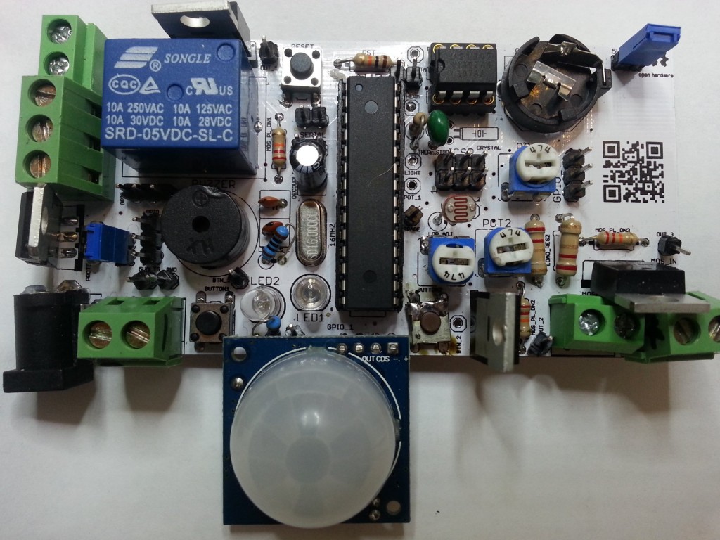
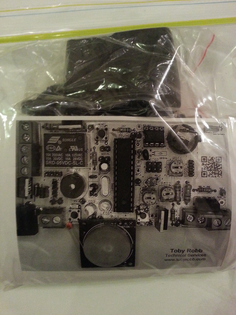
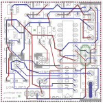
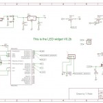
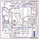
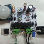
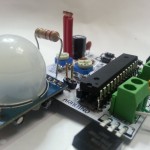
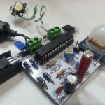
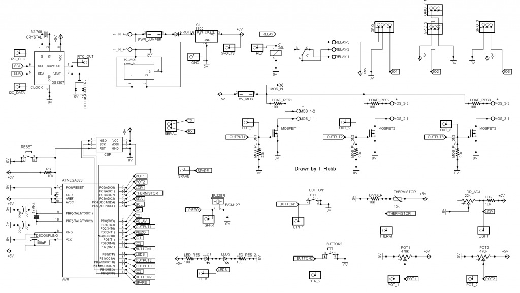 At first I just layed out the Atmega with its crystal and 2 caps. Then i thought I may as well add a voltage regulator and power cap as well.