Turning things on and off via SMS the easy way.
Have you ever wished you could turn something on or off after you’ve left the house?
Wether you left the computer on or you want to turn your remote computer or server on, being able to remotely control your devices is handy.
I have tried the hard wire and relays scenario and its too complicated.
Enter the remote sockets made by Watts Clever.
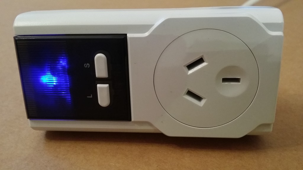
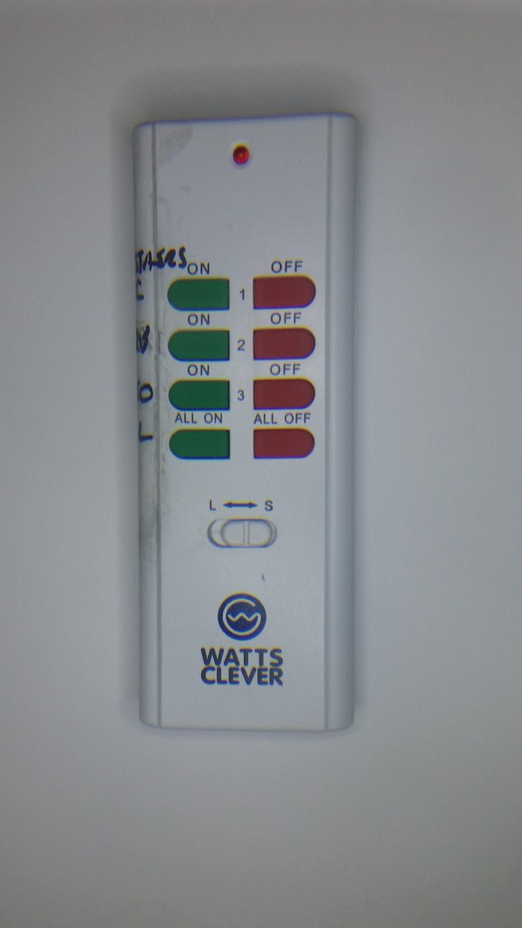
These sockets come with a handset that you can use to control them from within the house, much like a TV remote (great if you’re too lazy to get out of bed!). Although this remote uses common 433Mhz radio signalling.

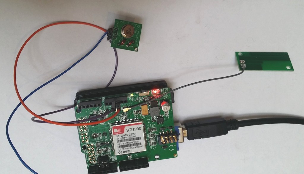
A nice library called rc-switch let’s you use a cheap ebay 433Mhz transmitter (<$5) to emulate the transmitter.
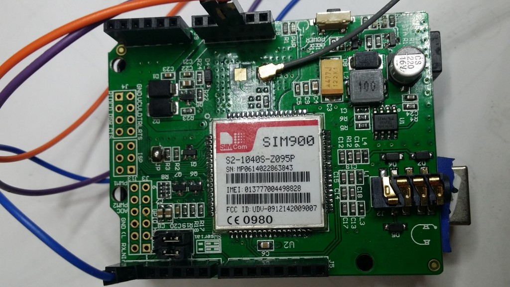
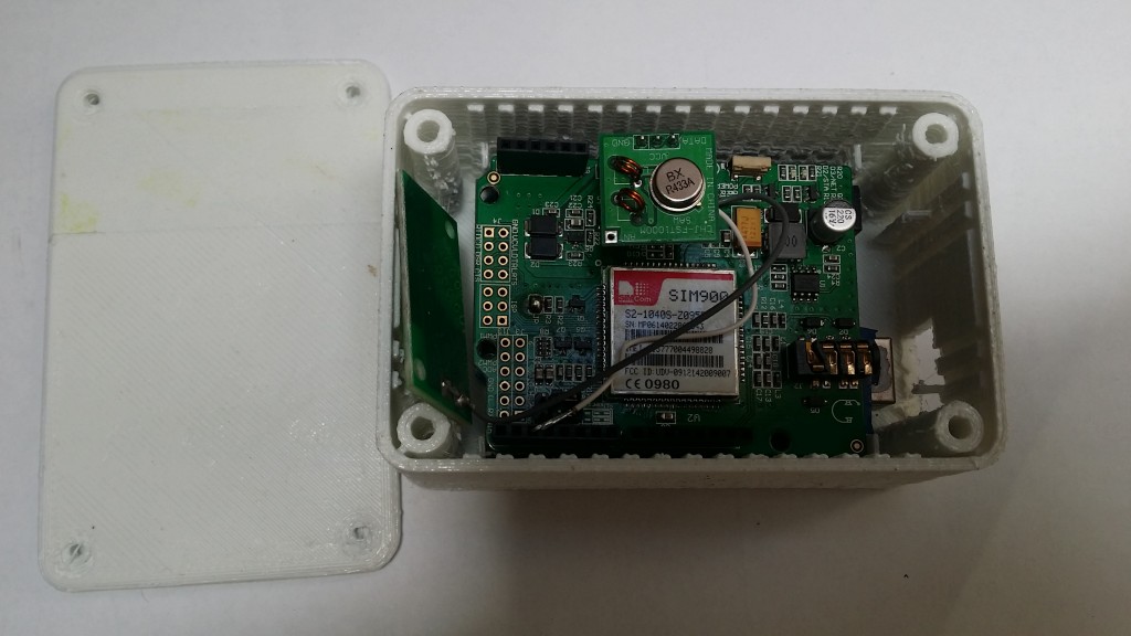
I have been using an SMS shield (like this) for the Arduino for a few different projects, It is a fully featured sim card phone (yes it can make calls!).
Put the two together and it’s easy enough to SMS a command to the board from your mobile phone (quite literally phoning your home!)
The Arduino reads the incoming text messages from the shield and sends the on/off codes to your Watts Clever sockets.
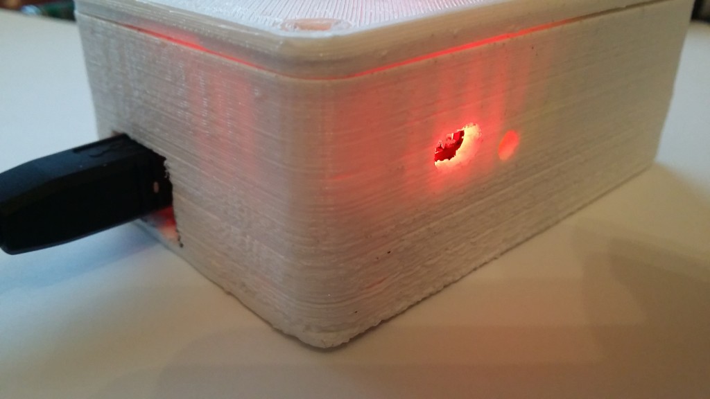
I have a printer, so I printed a simple box for it. I left a hole for the status lights and to turn the SMS shield on or off if i need to.
There is a hole for a USB plug and I just plug the cable into a wall wart USB power charger.
It can be pretty much anywhere in the house.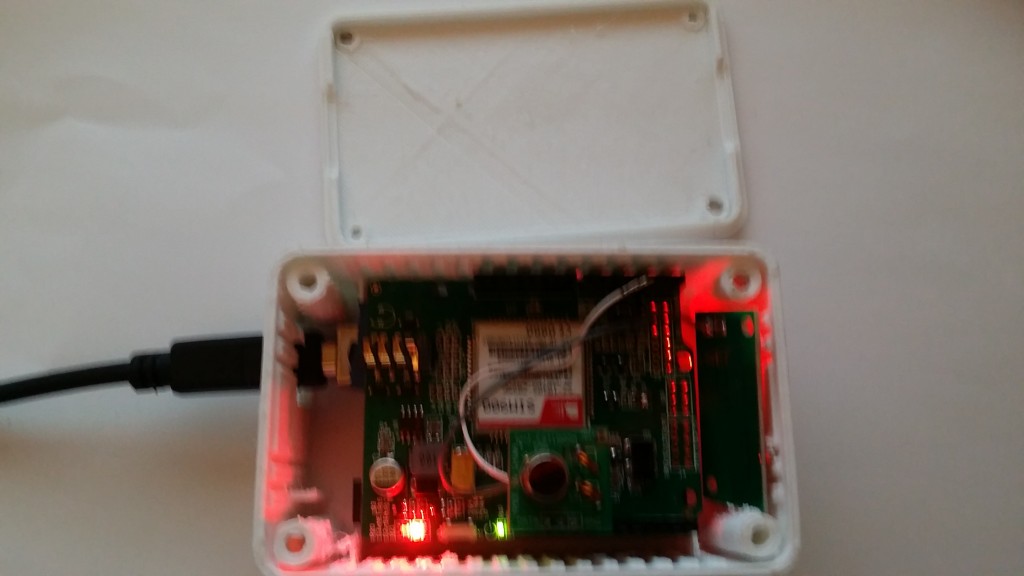
Here’s a summary video and a demonstration of it working.
Bill Of Materials
$40 Remote Socket (Set of 3 with remote, Jaycar)
$15 Arduino UNO
$35 SIM900 shield
$5 433mhz TX
$5 sim (New ALDI SIM 365 days of access 12c SMS’s)
______
$100
Well you may already have some remote controlled sockets as there are lots and lots of types on the market. If you do, the RCSwitch library has some examples to control other types.
See my git hub for the code..